Command and Programming Manual
Rev 1.7.2
Applicable to the public commands and data interfaces of HiPNUC IMU / AHRS / MRU products
Specific features are subject to the actual product model, firmware version, and delivered configuration
© 2016–2026 Beijing HiPNUC Electronic Technology Co., Ltd. All rights reserved. The information contained in this document is subject to change without notice.
Document Scope and Version
About This Manual
This manual is the Command and Programming Reference for HiPNUC IMU / AHRS / MRU products, intended for engineers who need to interface directly with the module, configure parameters, parse data, or integrate it into a higher-level system.
Applicable products: the public programming interfaces of HiPNUC IMU / AHRS / MRU standard products. Actual functionality depends on the specific product model, firmware version, and delivered configuration; sensors, CAN, RS-485, or MRU functions that are not enabled produce no corresponding output. This manual covers only the programming and data interfaces; for pin definitions, mechanical dimensions, power supply, and electrical specifications, refer to the hardware manual of the corresponding product.
Applicable firmware version: commands differ slightly between firmware versions. To check: send LOG VERSION over the serial port, or view it in the CHCenter host software, then select the corresponding manual according to the table below.
| Your hardware firmware version | Corresponding manual version | Where to get it |
|---|---|---|
| 1.7.1 and above | Rev 1.7.2 | This manual (this document) |
| 1.7.0 and below | Rev 1.3.0 | imu_cum_cn_150_170.pdf |
Note: version number conversion: the
APP_VERreturned byLOG VERSIONis an integer-encoded value: major version =APP_VER / 100, minor version =(APP_VER % 100) / 10, revision =APP_VER % 10(all divisions are integer divisions, rounded down). For example,APP_VER=172indicates firmware1.7.2. CHCenter displays the dotted version directly, and the two sources are consistent.
Manual structure:
| Chapter | Contents | Intended reader |
|---|---|---|
| 1 | Document Scope and Version | Confirm product, firmware, and reading path |
| 2 | Basic Conventions (frames / data types / status word) | Required reading before parsing data |
| 3 | Product Features and Configuration | Configure module functions |
| 4 | Magnetic Calibration and Magnetic Environment | Required reading before configuring 9-axis absolute heading |
| 5 | ASCII Command Reference | Quick command syntax lookup |
| 6 | Unified Data Dictionary | Cross-protocol physical-quantity semantics |
| 7 | Serial Binary Protocol (HI91 / HI83) | Parse binary output |
| 8 | Modbus RTU Protocol | Integrate RS-485 |
| 9 | CAN Protocol (J1939 / CANopen) | Integrate CAN |
| Appendix | A Attitude Mathematics / B Firmware Upgrade / C Bandwidth / D Factory Default Configuration / E Acronyms / F Development Resources | Reference |
Reader paths:
| Goal | Read first | Then read |
|---|---|---|
| Configure serial port, operating mode, mounting orientation | "Product Features and Configuration" | "ASCII Command Reference", Appendix "Factory Default Configuration" |
| Parse HI91 / HI83 binary data | "Basic Conventions", "Unified Data Dictionary" | "Serial Binary Protocol" |
| Integrate Modbus / J1939 / CANopen | "Basic Conventions", "Unified Data Dictionary" | "Modbus RTU Protocol", "CAN Protocol" |
| Use 9-axis absolute heading | "Operating Mode" | "Magnetic Calibration and Magnetic Environment" |
| Use MRU wave compensation output | "Wave Compensation / MRU Output" | "Unified Data Dictionary", "Serial Binary Protocol", "Modbus RTU Protocol" |
| Estimate bandwidth or check default configuration | Appendix "Output Bandwidth and Baud Rate" | Appendix "Factory Default Configuration" |
Notational conventions: command keywords, registers, and hexadecimal values are marked in monospace font; callout boxes use Warning (misuse may cause parsing errors, corrupted configuration, or abnormal accuracy/communication) and Note (supplementary explanations and examples); unified definitions of frames, byte order, and scale factors are given in "Basic Conventions"; common abbreviations and terms are listed in the Appendix "Acronyms and Glossary".
Quick Start Procedure
For first-time integration, it is recommended to complete the following minimal closed loop in order; after confirming the data is correct, proceed to the corresponding protocol chapter for system integration.
| Step | Action | Verification |
|---|---|---|
| 1 | Connect power, ground, and the communication interface according to the hardware manual | The host software or serial tool can open the port |
| 2 | Use 8N1 on the serial port, default 115200 bps; send LOG VERSION | PNAME, SN, and APP_VER can be read |
| 3 | Parse data according to the "Unified Data Dictionary" and the corresponding protocol chapter | At rest, acceleration magnitude is about 1 G and angular rate is close to 0 |
Basic Conventions
This chapter centrally defines the coordinate systems, attitude representations, heading conventions, data types and byte order, timestamps, and status words used throughout the manual. Every protocol chapter references this chapter and does not redefine them. Read this chapter before parsing any data.
Coordinate Systems and Direction Conventions
The module involves three right-handed coordinate systems:
| Frame | Symbol | Definition |
|---|---|---|
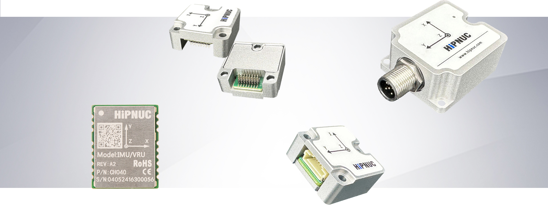
| Sensor frame | b (body frame) | Rigidly attached to the module; the X/Y/Z axis directions are printed on the housing/PCB silkscreen. All raw IMU quantities (acceleration, angular rate, magnetic field) are expressed in this frame. |
| User frame | — | Obtained by mapping the sensor frame through the mounting orientation URFR (see "Mounting Orientation"). With the default 24 it coincides with the sensor frame. |
| World frame | n (world frame) | The reference frame for attitude; defaults to East-North-Up ENU, switchable to North-West-Up NWU (CONFIG IMU COORD). |
East-North-Up (ENU): the X axis points East, the Y axis points North, the Z axis points Up. North-West-Up (NWU): the X axis points North, the Y axis points West, the Z axis points Up. Both are right-handed frames.
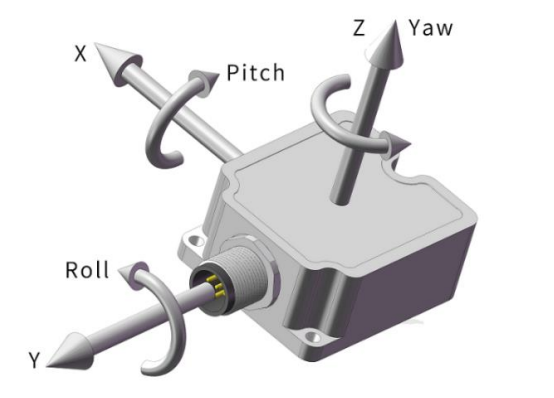
The positive rotation direction follows the right-hand rule: point the right thumb along the positive axis, and the direction in which the fingers curl is the positive rotation direction about that axis.
Attitude Representation

The module simultaneously outputs two attitude representations: Euler angles and quaternion.
- Euler angles: roll
roll, pitchpitch, headingyaw, in degrees. Under the default ENU, the 312 rotation order is used (first rotate about Z by yaw, then about X by pitch, and finally about Y by roll) — under this convention pitch is about the X axis and roll is about the Y axis (counter-intuitive; see Appendix A for details). After switching to NWU, the 321 order is used (about Z→Y→X), becoming roll about the X axis and pitch about the Y axis, opposite to ENU (see Appendix A for details). Ranges: roll ∈ [−180°, 180°], pitch ∈ [−90°, 90°], yaw ∈ [−180°, 180°]. - Quaternion: order WXYZ (
is the scalar part), representing the rotation from the body frame to the world frame.
The complete conversion formulas among quaternion ↔ Euler angles ↔ rotation matrix are given in "Appendix A".
Note: pitch ±90° singularity: when pitch approaches ±90°, the Euler angles have a gimbal-lock singularity and roll/yaw are no longer unique. For high-elevation attitudes, use the quaternion.
Heading (yaw) Convention
Warning: heading is the most easily confused point: the module's representation of yaw is not uniform across the different protocols/frames, so refer to the table below for understanding.
| Output location | Heading representation | Positive direction |
|---|---|---|
| HI91 / HI83 / CANopen | Raw yaw, range ±180° | Counter-clockwise positive (ENU) |
| Modbus YAW register | Raw yaw, range ±180° | Counter-clockwise positive |
| J1939 YAW message (first 4 bytes) | 0–360° | Clockwise positive |
| J1939 YAW message (last 4 bytes) | ±180° | Counter-clockwise positive |
Under the ENU and NWU world frames, the zero reference of yaw points in different directions, and the axis assignment of roll/pitch changes accordingly (312 for ENU, 321 for NWU; see "Attitude Representation"). After switching the frame (CONFIG IMU COORD), reconfirm the heading reference and the Euler-angle convention.
In 9-axis AHRS mode, yaw references magnetic north by default; this product does not output a true-north-corrected heading through the documented public interfaces. If your system requires a true-north heading, the host should apply a correction based on the deployment location, date, and a magnetic-declination model.
Data Types, Byte Order, and Scale Factors
Data types:
| Symbol | Meaning | Bytes |
|---|---|---|
| u8 / u16 / u32 / u64 | Unsigned integer | 1 / 2 / 4 / 8 |
| i8 / i16 / i32 | Signed integer (two's complement) | 1 / 2 / 4 |
| float | IEEE-754 single-precision float | 4 |
| double | IEEE-754 double-precision float | 8 |
Byte order:
| Protocol | Byte order |
|---|---|
| HiPNUC binary (HI91/HI83) | Little-endian (low byte first) |
| J1939 / CANopen | Little-endian |
| Modbus RTU | Big-endian (2 bytes per register, high byte first) |
Bit numbering convention: in this manual all bit fields (such as MAIN_STATUS and the HI83 data bitmap) use bit0 for the least significant bit (LSB), with bitN being the N-th bit counted from the least significant bit; thus the bit mask 0x00000FFF is bit0–bit11, and 0x000000FF is bit0–bit7.
Scale factor convention: in integer protocols the physical quantity is recovered with a scale factor, physical value = raw value × scale factor. For example, a Modbus acceleration raw value of 1000 with a scale factor of 0.00048828 gives a physical value = 0.488 G. Floating-point protocols (the float/double fields of HI91/HI83) are already in engineering units, with a scale factor of 1.
Warning: the same physical quantity has different types/scale factors/units across different protocols; see "Unified Data Dictionary" for details.
Time and Timestamps
The meaning of system_time in the data frame (u32 for HI91, in ms) varies with the synchronization state:
- UTC synchronization not completed: a local monotonic millisecond counter wrapping every 24 h, range
0~86,399,999 ms; it contains no date and does not represent absolute UTC; - UTC synchronization completed: the current-day UTC millisecond count (from 00:00:00 of the current day, wrapping every 24 h).
The synchronization state can be determined from the UTC_UNSYNC bit of MAIN_STATUS (see "MAIN_STATUS Status Word"). UTC synchronization is achieved via PPS + a serial time message; for hardware wiring and timing requirements see "Synchronization Function".
Current-day UTC millisecond timestamp:
| Item | Value |
|---|---|
| Range | 0 ~ 86,399,999 ms |
| Corresponds to | 00:00:00.000 ~ 23:59:59.999 |
| Resolution | 1 ms |
When converting to a display time, parse as hh=system_time/3600000, mm=(system_time/60000)%60, ss=(system_time/1000)%60, ms=system_time%1000. Conversion examples:
| system_time (ms) | Corresponding current-day UTC time |
|---|---|
| 0 | 00:00:00.000 |
| 3,661,000 | 01:01:01.000 |
| 43,200,000 | 12:00:00.000 |
| 86,399,999 | 23:59:59.999 |
Note: the timestamp contains no date or time-zone information and is interpreted as UTC+0 by default; if local time is required, the host should add the time-zone offset. HI83 additionally provides two time fields:
system_time_us(u64, local high-resolution microseconds) andutc(full year-month-day hour-minute-second); whether theutcfield is valid UTC is likewise determined byUTC_UNSYNC.
MAIN_STATUS Status Word
MAIN_STATUS is a 16-bit status word that appears in outputs such as HI91 and HI83, defined uniformly as follows
| Bit | Name | =1 meaning | =0 meaning |
|---|---|---|---|
| 0–2 | Reserved | — | — |
| 3 | WB_CONV | Gyro bias not converged, accuracy is poor (recommend staying static for 3~5 s) | Bias well converged |
| 4 | MAG_DIST | In 9-axis mode the runtime magnetic-field confidence is abnormal (field out of range, rotation verification not yet completed, or magnetic disturbance detected), and the heading angle may degrade to inertial hold | Magnetic-field confidence normal, or in 6-axis mode |
| 5 | ACC_SAT | Accelerometer range saturated currently or within the last 2 s | No accelerometer saturation for 2 consecutive s |
| 6 | GYR_SAT | Gyroscope range saturated currently or within the last 2 s | No gyro saturation for 2 consecutive s |
| 7 | ATT_CONV | Attitude estimate not sufficiently converged, accuracy is poor (recommend staying static for a moment) | Attitude accuracy normal |
| 8 | Reserved | — | — |
| 9 | STATIC | The device is judged to be static | The device is not judged to be static |
| 10 | MAG_AIDING | Magnetometer aiding mode enabled (9-axis mode); the actual magnetic update each cycle is still subject to magnetic-field confidence and algorithm de-weighting control | Magnetometer aiding mode off (6-axis mode) |
| 11 | UTC_UNSYNC | UTC not synchronized; system_time is a local 24 h wrapping millisecond counter | UTC synchronized; system_time is the current-day UTC milliseconds |
| 12 | SOUT_PULSE | The current data frame corresponds to one SOUT pulse output | The current frame does not correspond to a SOUT pulse |
| 13 | Reserved | — | — |
| 14–15 | Reserved | — | — |
Note: the
UTC_UNSYNCbit means "1 indicates not synchronized"; do not misread it literally as "synchronized".SOUT_PULSEis used to time-synchronize and align with the sampling timing of an external acquisition device or host.Reserved bits: reserved bits are used internally by the firmware and their values are not guaranteed to be 0; the client should mask and ignore all reserved bits and only evaluate the bits defined in this table, to ensure forward compatibility.
Product Features and Configuration
This chapter introduces the module's configuration items, use cases, and operating procedures by function. For specific command syntax, see "ASCII Command Reference"; for output data formats, see "Unified Data Dictionary" and the subsequent protocol chapters.
Operating Mode (Attitude / Heading Profile)
The module selects the attitude / heading profile via CONFIG ATT MODE (see "CONFIG Configuration Commands"). The common public profiles are as follows:
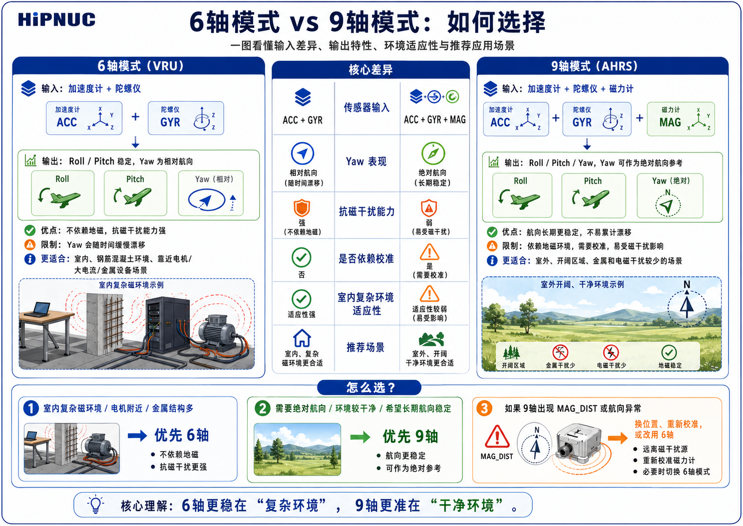
- 6-axis (VRU) mode: Uses only the accelerometer + gyroscope, outputting relative heading (heading is 0 at power-on), unaffected by magnetic interference, suitable for magnetically complex scenarios such as indoors, robotics, and near motors.
- 9-axis (AHRS) mode: Fuses the magnetometer, outputting absolute heading (relative to magnetic north). It must be used in a clean magnetic environment with magnetic calibration completed (see "Magnetic Calibration and Magnetic Environment").
- Dedicated motion profiles: Optimized for specific body motion constraints, such as humanoid robots, low-speed ground platforms, and low-dynamic inclinometers. For the specific selectable values, see "CONFIG ATT MODE".
Warning: Use 9-axis with caution indoors/on robots: Indoor environments and motor magnetic fields easily interfere with the magnetometer, causing heading errors. For such scenarios, 6-axis mode is recommended as the preferred choice.
Mounting Orientation (URFR)
CONFIG IMU URFR <CODE> (see "CONFIG Configuration Commands") is used to declare the module's mounting orientation, aligning the output to the user's desired Right-Front-Up direction.
CODE is written as a three-digit number ABC (a 2-digit value is equivalent to padding with a leading zero, e.g., 24 = 024): A/B/C indicate which sensor-frame direction the user-frame X/Y/Z axes correspond to, respectively:
| Digit | Direction | Digit | Direction |
|---|---|---|---|
| 0 | +X | 1 | −X |
| 2 | +Y | 3 | −Y |
| 4 | +Z | 5 | −Z |
The right-handed-frame constraint must be satisfied (X × Y = Z). When looking up the table, simply select the corresponding command based on the module's physical orientation; there is no need to manually apply the "user axis → sensor direction" encoding rule above. In the table below, for the 24 valid mountings, "Right / Front / Up" refers to the actual pointing of the sensor X / Y / Z axes in the body (user) frame (which is the inverse viewpoint of the encoding rule above; if you need a custom orientation not in the table, derive it according to the encoding rule starting from the "user axis", and do not directly copy the sensor-axis observation directions of this table):
| IMU axis pointing (X, Y, Z) | Command | Description |
|---|---|---|
| Right, Front, Up | URFR 24 | Default horizontal mounting (=024) |
| Right, Back, Down | URFR 35 | Flipped upside-down about X (=035) |
| Right, Down, Front | URFR 43 | Side mounting (Right+Down) |
| Right, Up, Back | URFR 52 | Side mounting (Right+Up) |
| Left, Front, Down | URFR 125 | X reversed, Z downward, inverted |
| Left, Back, Up | URFR 134 | X/Y reversed, Z upward |
| Left, Up, Front | URFR 142 | Left-facing vertical mounting, Y up |
| Left, Down, Back | URFR 153 | Left-facing vertical mounting, Y down |
| Front, Right, Down | URFR 205 | Forward mounting, X along the vehicle nose |
| Back, Right, Up | URFR 214 | Backward mounting, Y to the right |
| Up, Right, Front | URFR 240 | Vertical mounting, X up |
| Down, Right, Back | URFR 251 | Vertical mounting, X down |
| Front, Left, Up | URFR 304 | Forward mounting, Y to the left |
| Back, Left, Down | URFR 315 | Backward inverted mounting |
| Down, Left, Front | URFR 341 | Left-facing vertical mounting, X down |
| Up, Left, Back | URFR 350 | Left-facing vertical mounting, X up |
| Front, Up, Right | URFR 402 | Forward vertical mounting, Z to the right |
| Back, Down, Right | URFR 413 | Backward vertical mounting |
| Down, Front, Right | URFR 421 | Vertical mounting, X down, Z to the right |
| Up, Back, Right | URFR 430 | Vertical mounting, X up, Z to the right |
| Front, Down, Left | URFR 503 | Forward vertical mounting, Z to the left |
| Back, Up, Left | URFR 512 | Backward vertical mounting |
| Up, Front, Left | URFR 520 | Vertical mounting, X up, Z to the left |
| Down, Back, Left | URFR 531 | Vertical mounting, X down, Z to the left |
The world frame (ENU/NWU) is switched via CONFIG IMU COORD; see "CONFIG Configuration Commands".
Attitude Calibration
CONFIG ATT RST (see "CONFIG Configuration Commands") is used for user attitude zero-point operations: heading reset, relative zeroing, auto-leveling, and cancel leveling. The device must be stationary during execution; auto-leveling takes effect only when the device is placed nearly level and upright.
CONFIG USRCAL (see "CONFIG Configuration Commands") is used for user-level gyro scale calibration, calibrating the gyro Z-axis scale factor to reduce the long-term heading accumulation error of a horizontally rotating body. This feature is suitable for controllable horizontal rotation scenarios such as AGVs, large horizontally moving robots, and turntables; it is not suitable for handheld arbitrary rotation or scenarios where the rotation angle cannot be accurately measured. Operating steps:
- Place the module together with the body on level, flat ground, with a stable ambient temperature and no strong vibration;
- Send
CONFIG USRCAL START <ANGLE>(angle 360°~3600°); - Rotate horizontally at a constant 20~100 deg/s through the set angle (any direction, no pausing, no abrupt change);
- After the rotation is complete, send
CONFIG USRCAL STOP; a successful return isOK. It is recommended that the actual rotation angle, controlled manually or by a turntable, not deviate by more than ±5°; if the actual angle deviates too much from the set angle, the calibration will introduce a new scale error.
Common failure causes: improper rotation (too fast, too slow, pausing midway, or obvious wobbling), environmental vibration, and the actual rotation angle deviating too much from the set value.
Synchronization Function
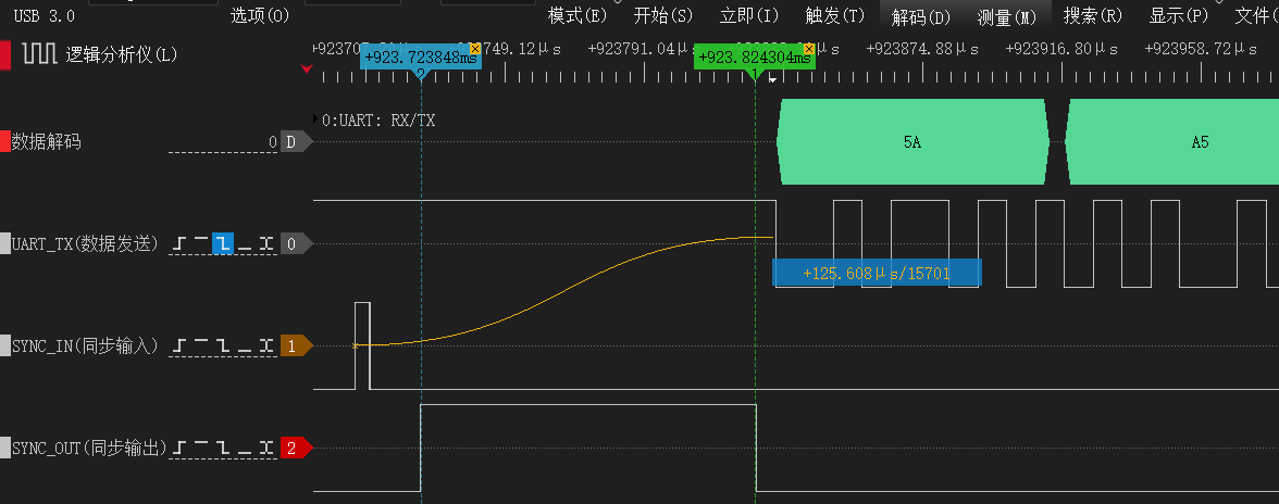
The module's synchronization function relies on the SYNC_IN/PPS and SOUT pins and covers three categories of use. The figure below shows logic-analyzer-measured waveforms, taking the SYNC_IN trigger mode as an example: a rising edge on SYNC_IN/PPS triggers the output of that frame; the module first outputs the SOUT pre-frame pulse before sending the data frame, and the data frame follows immediately after the falling edge of the pulse. Note that the SOUT pre-frame pulse is generated for every output data frame and does not depend on the SYNC_IN trigger (see "SOUT Synchronous Output" for details).
SYNC_IN Synchronous Data Trigger
Triggers data output via an external pulse. After the module detects a rising edge on the SYNC_IN/PPS pin, it outputs the data frame that has been configured for synchronous trigger mode; that frame is no longer sent periodically.
- Serial protocol: Use
LOG <MSG> ONMARK 1to configure the target frame as pulse-triggered (see "LOG Command"). - J1939: Set the transmission period of the target PGN to
0x8000(see "J1939 Configuration Protocol").
When this function is not used, the pin is recommended to be left floating or grounded.
PPS Standard Pulse Synchronization
Using the SYNC_IN/PPS pin to receive an external 1PPS pulse, combined with receiving a time message over the serial port, can provide precise UTC time synchronization for delivery configurations with this function enabled. After the module detects a valid PPS rising edge and receives a matching time message, its internal clock automatically aligns to the UTC whole second.

| Parameter | Description | Valid Range | Recommended |
|---|---|---|---|
| t0 | Interval between rising edges of adjacent pulses | 990~1010 ms | 1000 ms |
| t1 | Pulse high-level time (pulse width) | 1~100 ms | 10~50 ms |
| t2 | Time message transmission time | Related to baud rate | — |
| t3 | Delay of the time message relative to the most recent pulse rising edge | Within the firmware pairing window | 0~100 ms |
Warning: Core requirement: The time message used for synchronization must carry the whole-second UTC time and arrive within the pairing window of the most recent PPS. In engineering practice, it is recommended to send it as close as possible to the PPS rising edge and to keep the phase stable.
Hardware and Interface Requirements:
SYNC_IN/PPS: Rising edge active; high level ≤ 5V (TTL/CMOS compatible).- Serial
RX: Time message frequency 1~10 Hz (1 Hz recommended); the baud rate must match the module's current configuration; only firmware-defined UTC time messages are supported.
The module extracts only the UTC time (hour/minute/second/millisecond) and date (year/month/day) fields from the time message for synchronization, ignoring all other fields. After successful synchronization, the meaning of system_time is described in "Time and Timestamp". This input message format is part of the delivery configuration; if PPS synchronization is required, refer to the delivery documentation of the corresponding product.
SOUT Synchronous Output
SOUT is the synchronous output pin. It is low when there is no data output; before a data frame begins transmitting, it first outputs a high pulse, and the data follows immediately after the falling edge of the pulse. It can be used to trigger devices such as cameras to achieve strict time synchronization. The SOUT_PULSE bit of the corresponding data frame's MAIN_STATUS (see "MAIN_STATUS Status Word") is set to 1.
Multi-function IO Multiplexing (PMUX)
The module provides multiple multi-function pins (IOx), each with a default multiplexed function, which can also be remapped via CONFIG PMUX<n> IO<m> (e.g., CONFIG PMUX2 IO3, see "CONFIG Configuration Commands"):
| Function | Name | Direction | Description | Default IO |
|---|---|---|---|---|
| PMUX1 | SYNC_IN/PPS | Input | Synchronous pulse input (see "Synchronization Function") | IO1 |
| PMUX2 | SOUT | Output | Pre-frame sync pulse output (see "SOUT Synchronous Output") | IO2 |
| PMUX3 | LED | Output | Operating status indicator | IO5 |
Note: Not all IO pins are brought out on a specific product; see the corresponding product hardware manual for details.
Product-Specific Features
The following features are supported only on specific models or delivery configurations; other models may skip this section.
Inclinometer Output (Only HI50 and Certain Models)
The inclinometer outputs the body's tilt relative to the horizontal plane in "inclination" semantics, suitable for scenarios such as platform leveling, angle monitoring, and construction machinery attitude. The inclination is derived from the attitude solution:
- X-axis inclination: Based on roll, with a range of ±180° dual-axis and a configurable 0–360° single-axis;
- Y-axis inclination: Based on pitch, with a range of ±90°.
Output locations: HI83 (bit9), Modbus (0x4A / 0x4B), J1939 (PGN 0xFF4A), CANopen (TPDO7); see "Unified Data Dictionary" for the scale factor of each protocol.
Direction and zero point: The output direction of each axis can be independently reversed (0=default, 1=reversed; for J1939 configuration see "J1939 Configuration Protocol"); the inclination zero point is achieved via "attitude relative zeroing" (CONFIG ATT RST 2, see "CONFIG Configuration Commands"; the CANopen equivalent is 0x20A5 in "CANopen Configuration Commands"). After configuration, a reset or power cycle is recommended to recheck.
Wave Compensation / MRU Output (Heave / Surge / Sway)
The MRU delivery configuration is used to estimate the periodic motion of ships or offshore platforms, outputting three-axis displacement and main-frequency information:
| Motion Axis | Description | Output |
|---|---|---|
| Heave | Heave | Vertical displacement, frequency |
| Surge | Surge | Bow-stern direction displacement, frequency |
| Sway | Sway | Left-right direction displacement, frequency |
The data is output via HI83 (bit10 displacement / bit11 frequency) or Modbus (0x4E–0x50 displacement, 0x51–0x53 frequency); see "Unified Data Dictionary". The MRU output reflects the periodic-motion estimation result and is not used as absolute position or track information.
Application scenarios: Ship dynamic monitoring and attitude control, offshore engineering operation compensation (lifting, docking), wave characteristic research, and offshore platform attitude stability analysis.
Usage limitations:
Warning: Important limitations
- Applicable only to periodic reciprocating motion; the following cases usually cannot be accurately measured: motion with too long a period (> 30 s), unidirectional linear motion, and step-like displacement.
- Zero-mean assumption: The algorithm assumes that the long-term average of the displacement is 0.
- Initialization time: A stable 5~20 wave periods are required as the initialization time to obtain correct results.
- Frequency response range: The typical wave period is 3~20 s; accuracy decreases beyond this range.
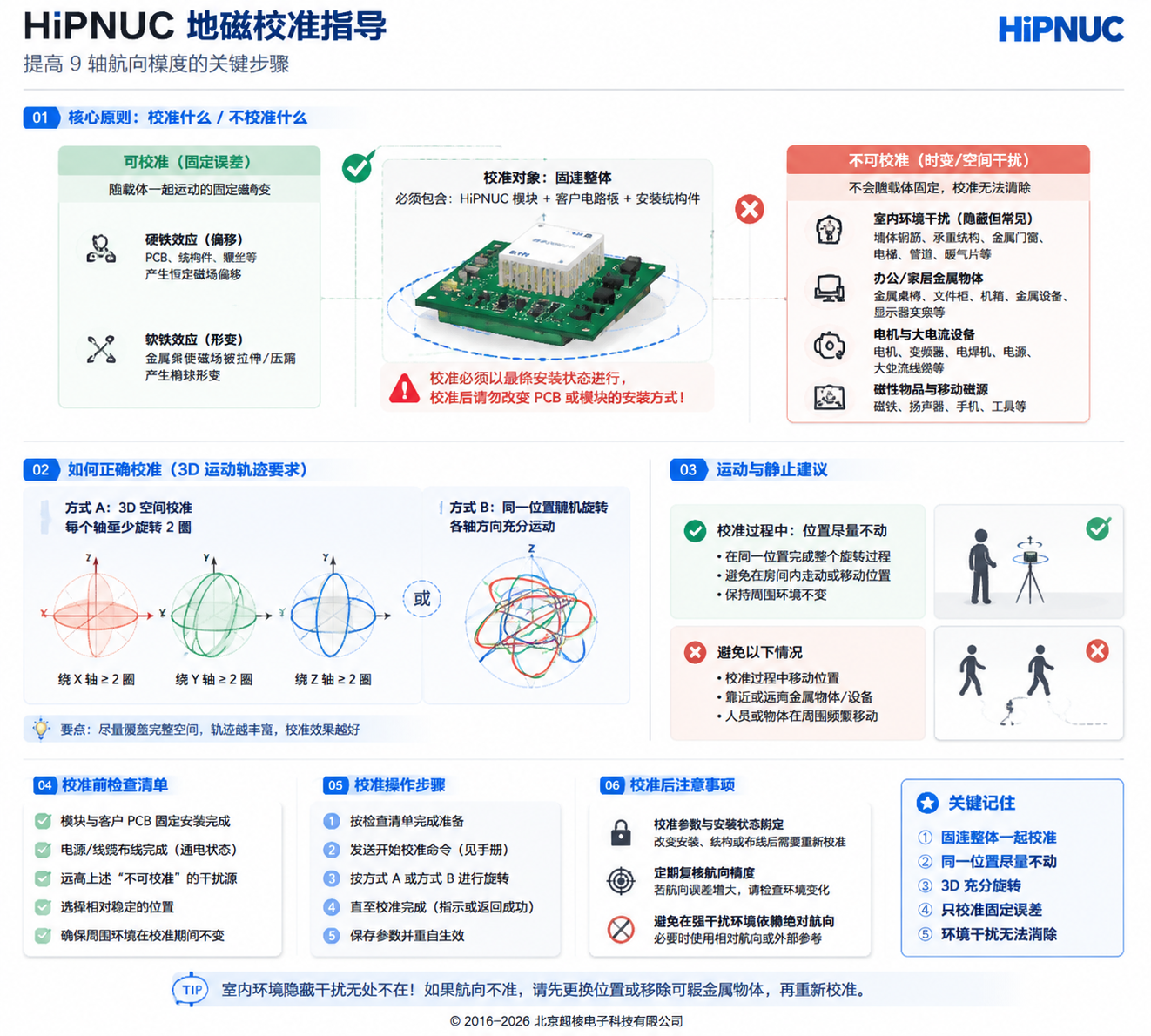
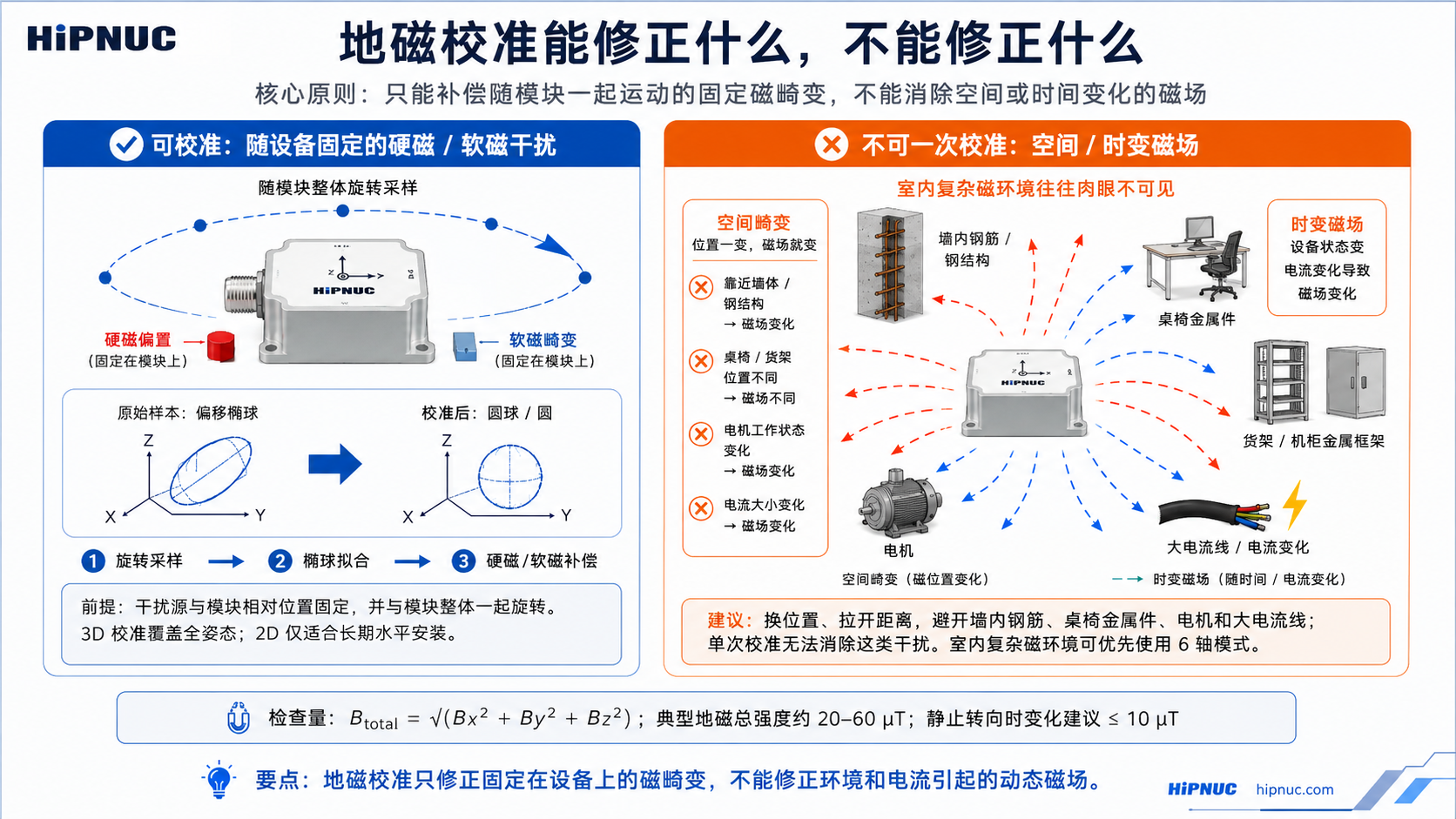
Magnetic Calibration and Magnetic Environment
Magnetic calibration removes the hard-iron/soft-iron disturbances that move together with the module, and is a prerequisite for obtaining a reliable heading angle in 9-axis (AHRS / magnetometer-aided absolute heading) mode. Magnetic calibration is not required when using 6-axis (VRU) mode only.
Note: Procedure overview: Switch to 9-axis mode → slowly rotate each axis together with the carrier in a clean magnetic environment → observe the progress with
LOG MCAL STAT→ rotate one full turn to verify that the heading angle is continuous and free of jumps.
Applicable Scenarios
9-axis mode is recommended when all of the following conditions are met simultaneously:
- Complete at least one user magnetic calibration before using 9-axis mode for the first time;
- The operating environment has no obvious spatial magnetic distortion (an open outdoor area is recommended; an indoor environment with a complex magnetic field makes good results hard to guarantee);
- The relative position between the module and its mounting carrier (PCB, enclosure, robot, etc.) stays fixed during use.
Warning: Prefer 6-axis indoors: Indoor spatial magnetic distortion cannot be removed by calibration; even if calibration succeeds, the 9-axis heading accuracy may still be worse than in 6-axis mode. For scenarios such as equipment rooms, laboratories, workshops, and underground garages, 6-axis mode is recommended.
Run-time trustworthiness assessment:
| Status bit | Meaning | Host handling recommendation |
|---|---|---|
MAIN_STATUS.MAG_AIDING=1 | Magnetic field participates in heading estimation | Prerequisite for absolute heading availability; still combine with environment assessment |
MAIN_STATUS.MAG_AIDING=0 | Magnetic field does not participate in heading estimation | yaw is handled as 6-axis relative heading and will drift over the long term |
MAIN_STATUS.MAG_DIST=1 | Magnetic interference or abnormal magnetic field state detected | Absolute heading is not trustworthy; investigate the environment first or switch to 6-axis mode |
The control system should not judge reliability from the yaw value alone; it should also check the magnetometer-aiding and magnetic-interference status bits in MAIN_STATUS.
Calibration Steps
Step 1: Switch the operating mode
First configure the module to 9-axis mode (CONFIG ATT MODE 1, see "Operating Mode"), then reset or power-cycle, and confirm that magnetometer-aided mode is enabled via MAIN_STATUS.MAG_AIDING=1 or by reading back the configuration.
Step 2: Check the calibration environment
Common sources of magnetic interference: magnets, speakers, magnetic screws, iron furniture, steel fixtures, vehicle chassis, computer monitors, motors and transformers, high-current cables, mobile phone chargers, structural building rebar, etc.
| Environment level | Requirement |
|---|---|
| Best | Open outdoor area, away from buildings and vehicles (distance > 5 m) |
| For temporary verification only | An indoor area away from steel structures, motors, high-current cables, and magnets; mass-production acceptance should use an open outdoor area, or a fixed site already validated by B_total and heading-rotation verification |
Warning: Whole-assembly calibration principle: If the module has already been soldered onto the product PCB, uses a magnetic enclosure, or has already been installed on a robot/mechanical equipment, you must rotate and calibrate the entire assembly that is rigidly fixed to the module together. Calibrating the module alone and then installing it into the product will invalidate the calibration.
Step 3: Perform the calibration
Send the calibration command: CONFIG MCAL START (requires firmware version ≥ 1.7.0). Once the module enters the calibration process, it collects three-axis magnetic field samples during rotation and automatically fits the hard-iron/soft-iron compensation parameters; no stop command needs to be sent.
Rotation essentials:
- Keep the position essentially unchanged within as small a spatial range as possible, and slowly rotate only the module; if the module is already rigidly fixed to the carrier, rotate the module and carrier together as a whole;
- Cover as many attitude directions as possible; for 3D calibration it is recommended to rotate each axis at least 360° (2 to 3 turns recommended), at a uniform speed, with a recommended 20 to 100 deg/s (about 4 to 18 seconds per turn), avoiding staying in the same attitude for a long time;
- Calibration usually takes 30 to 60 s.
Recommended rotation scheme: rotate 2 turns about the X axis → 2 turns about the Y axis → 2 turns about the Z axis; or rotate randomly, ensuring every axis undergoes sufficient angular variation while keeping the position as fixed as possible.
Note: Planar mounting (2D) calibration: For mountings that stay essentially level during operation and rotate mainly about the vertical axis (such as AGVs, turntables, vehicles), planar calibration can be started via the command line
CONFIG MCAL START 2D, requiring rotation only about the vertical axis. The standard CHCenter calibration button runs the ordinaryCONFIG MCAL STARTprocess; to force 2D, use the command line or the configuration method specified in the delivery notes. 2D calibration is not detected automatically and must explicitly carry the2Dparameter; it updates only the horizontal-plane parameters and retains the existing Z-axis hard-iron compensation. If a valid 3D calibration has never been performed, the Z-axis hard-iron environment changes, or the carrier will pitch/roll noticeably, use 3D calibration.
Step 4: Query the calibration status
Send LOG MCAL STAT. Example response:
STAT=3
PROGRESS=100
QUALITY=72
OK| STAT | Status | Recommended action |
|---|---|---|
| 0 | Currently idle | A new calibration can be started |
| 1 | Calibrating | Continue rotating the module; if the module is already rigidly fixed to the carrier, rotate the module and carrier together as a whole |
| 3 | Calibration completed | Calibration succeeded, ready for normal use |
| 4 | Calibration failed | Refer to the troubleshooting procedure and recalibrate |
PROGRESS: ranges 0 to 100, indicating magnetic-sample coverage, not time progress; it shows at most 99 while running and only shows 100 after STAT=3. QUALITY: ranges 0 to 100, indicating the result quality after fitting is completed; manual calibration requires QUALITY ≥ 50 to be judged successful (STAT=3 already satisfies this), and a higher value means a better fit; when STAT=1 it is not used as the quality criterion for the current calibration and may still be the result of the previous calibration.
After calibration succeeds, the hard-iron/soft-iron compensation parameters are immediately applied to the AHRS estimation and written to non-volatile storage; there is no need to run SAVECONFIG separately, nor is a reset required for them to take effect. It is recommended to perform another heading-rotation verification after reset or power-cycle to confirm that the parameters retained through power-down still suit the current mounting and environment.
Step 5: Verify the calibration result
- After calibration is complete, place the module level and slowly rotate it one full turn (360°);
- Observe the heading angle output: ideally it should vary continuously with the rotation, without unexpected jumps; if the protocol output range is ±180°, wrap-around at the ±180° boundary is allowed; if the output range is 0° to 360°, wrap-around at the 0/360° boundary is allowed;
- If the error relative to the reference heading or the closure error over one full turn exceeds ±5°, a non-boundary wrap-around jump appears, or the heading angle does not change with rotation, refer to the troubleshooting procedure below.
Troubleshooting Procedure
When calibration fails (STAT=4) or the verification result is abnormal, check item by item according to the table below, moving to the next item only after the previous one passes (total magnetic field strength B_total = √(Bx² + By² + Bz²), computed from the mag_b three axes):
| Order | Check item | Pass criterion | Handling when failed |
|---|---|---|---|
| 1 | Read the total magnetic field strength B_total at rest | 20–60 μT | Below 20 μT (shielded / too weak) or above 60 μT (a magnet nearby / too strong) → move away from the interference source or change location, then recalibrate |
| 2 | Whether attitude coverage is sufficient | 3D: sufficient coverage on each axis, recommended ≥ 360° per axis; 2D: more than one full turn around the vertical axis in the horizontal plane; rotation speed recommended 20–100 deg/s | Insufficient coverage or staying in the same attitude for a long time → redo the rotation per the essentials, then recalibrate |
| 3 | Change of B_total when changing orientation at the same location | Difference between maximum and minimum ≤ 10 μT | Exceeds 10 μT (spatial magnetic distortion present); do not judge by the variation of a single axis Bx/By/Bz → change location, or switch to 6-axis mode |
| — | All three items pass but still abnormal | — | Perform calibration again in a clean environment |
Frequently Asked Questions
| Failure cause | Typical symptom | Solution |
|---|---|---|
| Excessive ambient magnetic interference | STAT=4 or heading-angle jumps | Move to an open outdoor area to calibrate |
| Non-standard rotation motion | PROGRESS grows slowly or stalls | Ensure each axis is rotated sufficiently at a uniform speed |
| Position moved during rotation | Calibration completes but accuracy is poor | Keep the position fixed during calibration and rotate the attitude only |
| Module-carrier position changed | Heading-angle error increases after reinstallation | Recalibrate the module and carrier together as a whole |
Precautions
Warning: Indoor magnetic field limitation: Indoor spatial magnetic interference cannot be removed by calibration, and the 9-axis heading accuracy depends on the actual degree of magnetic distortion; for the principle, see "Magnetic Interference Types and Calibration Boundaries" in this chapter.
Warning: Fixed-mounting requirement: Sources of magnetic interference must keep a fixed relative position to the module. When the module is mounted on a magnetically permeable rigid body (robot/mechanical equipment/vehicle/ship/tripod/PCB, etc.), the entire system must be rotated and calibrated together; no relative displacement should occur during use, and recalibration is required once they are separated.
Warning: Motor and current influence: If the magnetic field produced by motors, cables, and drivers varies with load, current, or speed, it is a time-varying disturbance and cannot be removed by a single magnetic calibration. Calibration is recommended while the motor is stopped; only when the operating state is stable and the magnetic field is fixed relative to the module may calibration be done in that operating state. If the operating state changes significantly, increase the distance or use 6-axis mode.
Calibration Frequency and Mode Selection
Calibration frequency recommendations:
- For a fixed mounting in a stable environment, a single first-time calibration is sufficient;
- For mobile applications, recalibration is recommended each time the environment changes;
- Recalibrate when the relative position between the module and the carrier changes;
- For long-term use (> 1 year), calibration once a year is recommended;
- Recalibrate immediately when an abnormal heading-angle error appears.
Mode selection recommendations:
| Application scenario | Recommended mode | Reason |
|---|---|---|
| Open outdoor environment (UAVs, etc.) | 9-axis | Low magnetic interference; an absolute heading angle can be obtained |
| Indoor environment (AGVs, robots, etc.) | 6-axis | Indoor magnetic interference is large; 6-axis is more stable |
| Near motors / electromagnetic equipment | 6-axis | Electromagnetic interference cannot be removed by calibration |
| Absolute heading angle required | 9-axis | Must ensure a stable ambient magnetic field and a completed calibration |
| Only relative heading angle required | 6-axis | The 6-axis heading angle is 0 at power-up, suitable for relative measurement |
Magnetic Interference Types and Calibration Boundaries
Magnetic interference can be divided into two major categories by "whether it moves together with the sensor". Only interference that moves with the sensor can be removed by user magnetic calibration; spatial magnetic distortion cannot be removed no matter how you calibrate.
| Magnetic interference type | Interference moving with the sensor | Spatial magnetic distortion |
|---|---|---|
| Characteristics | The interference source moves as the sensor moves | The interference source does not move with the sensor |
| Sub-categories | Hard-iron (rigidly attached magnets / PCB / metal enclosure), soft-iron (rigidly attached permeable metal), sensor calibration error | Spatial distortion (rebar / furniture / appliances), temporal distortion (motor / current variation) |
| Typical interference sources | PCB rigidly fixed to the module, metal enclosure, UAV frame, etc. | Furniture, household appliances, cables, building rebar structures, etc. |
| Can it be calibrated | Yes | Impossible |
| Mitigation measures | Can be removed by user magnetic calibration | Calibration cannot remove it and it significantly increases heading-angle error |
ASCII Command Reference
Module configuration uses serial ASCII string commands, each terminated by a carriage-return/line-feed \r\n (similar to AT commands). This chapter is the authoritative syntax reference for the commands; for functional background and operating procedures, see "Product Features and Configuration".
Command Format and Conventions
- Case: command keywords are uppercase.
- Separation: parameters are separated by spaces, e.g.
CONFIG IMU URFR 24(notURFR=24). - Effect and saving:
- Communication commands (
SERIALCONFIG,LOG ENABLE/DISABLE,LOG <MSG> ONTIME/ONMARK) usually take effect immediately; - Long-term configurations are typically persisted once written, but some configurations are loaded only after a reset or power cycle; refer to each command's description and the appendix "Factory Default Configuration" for specifics;
SAVECONFIGsaves all parameters to flash; it is recommended to keep it at the end of the configuration flow for compatibility across firmware versions;- Restore-type commands (
FRESET) save automatically and trigger a reset.
- Communication commands (
- Recommended flow: send configuration → reset or power cycle if necessary → read back to confirm.
Note: This chapter lists common public commands. Compatibility or custom commands are governed by the actual delivery documentation.
Command Overview
| Command | Function | Effect |
|---|---|---|
REBOOT | Reset the module | Immediate |
SAVECONFIG | Save all parameters to flash | Immediate |
SERIALCONFIG | Set the serial baud rate | Immediate |
FRESET | Restore factory defaults | Immediate (saves automatically and resets) |
CONFIG | Configure various parameters and operating modes | Per sub-command |
LOG | Query information / configure data output | Per sub-command |
System Commands
REBOOT — Reset the module. Example: REBOOT
SAVECONFIG — Save all parameters to flash. The automatic-save policy may differ across firmware versions, so the host configuration flow should execute this command once after parameter writes are complete.
Example: SAVECONFIG
SERIALCONFIG — Set the serial baud rate. Format: SERIALCONFIG [<COM>] <BAUD>
- When
<COM>is omitted, the currently connected serial port is configured; when specified (e.g.COM2), the corresponding serial port is configured. - Supported
BAUDvalues (9 in total):48009600192003840057600115200230400460800921600
Examples: SERIALCONFIG 115200, SERIALCONFIG COM2 921600
Warning: This command takes effect immediately; after execution you must switch the host to the new baud rate to continue communication.
FRESET — Restore default user configuration; after execution it saves automatically and resets, so use it with caution. Example: FRESET
CONFIG Configuration Commands
Note: The effect timing of
CONFIGvaries; long-term configurations are persisted once written, but it is generally recommended to read them back for verification after a reset or power cycle. The current public configuration can be read back withLOG COMCONFIG,LOG USRCONFIG, andLOG MCAL STAT(see "LOG Commands").
Event-type or runtime configurations such as ATT RST, IMU URFR, PMUX, and MCAL usually act immediately; long-term configurations such as ATT MODE and IMU COORD are saved when written and loaded after a reset or power cycle.
Operating Mode — CONFIG ATT MODE <VAL>
| VAL | Mode |
|---|---|
| 0 | VRU (6-axis) |
| 1 | AHRS (9-axis, magnetometer-aided) |
| 4 | Dedicated to humanoid robots |
| 5 | Low-speed ground platform (lawn mowers / agricultural machinery / construction machinery, etc.) |
| 7 | Low-dynamic / inclinometer |
Other delivered modes are governed by the corresponding product documentation. For background, see "Operating Mode".
Attitude Calibration — CONFIG ATT RST <VAL>
The device should be stationary during execution; otherwise errors are introduced.
| VAL | Action |
|---|---|
| 1 | Heading reset: set the current heading angle to zero |
| 2 | Set relative zero: set the current Pitch and Roll to zero |
| 3 | Auto-leveling: only when both Pitch/Roll are close to 0° (decision threshold 5°), level Pitch/Roll to 0°,0°; otherwise the command has no effect |
| 5 | Cancel leveling: restore absolute angles |
Note: Other values are for reserved or compatibility purposes and are not used as a public interface.
Mounting Orientation — CONFIG IMU URFR <CODE>
CODE is a 2–3 digit orientation code that indicates the mounting orientation of the user frame relative to the sensor frame. For the complete code table (24 legal right-handed frames), see "Mounting Orientation". Example: CONFIG IMU URFR 24 (default horizontal mounting)
World Frame — CONFIG IMU COORD <VAL>
| VAL | Frame |
|---|---|
| 0 | East-North-Up (ENU, default) |
| 4 | North-West-Up (NWU) |
Multi-function IO Multiplexing — CONFIG PMUX<n> IO<m>
n=1~3 is the multiplexed function, and m=1~5 is the target pin. For function definitions, see "Multi-function IO Multiplexing". Example: CONFIG PMUX2 IO1 (set IO1 as synchronous output)
Magnetic Calibration — CONFIG MCAL START [2D]
Start a manual magnetic calibration. Without the 2D parameter it is a 3D calibration; CONFIG MCAL START 2D is a planar (rotation about the vertical axis only) calibration. For status queries, see LOG MCAL STAT. For the complete procedure, see "Magnetic Calibration and Magnetic Environment".
User-level Gyro Calibration — CONFIG USRCAL START <ANGLE> / CONFIG USRCAL STOP
ANGLE: calibration angle, in degrees, with a valid range of 360°~3600°; out-of-range values return an error.- After the rotation is complete, send
CONFIG USRCAL STOP; on success it returnsOK, otherwise it returnsERR(usually indicating that the main rotation axis is ambiguous or that the scale factor is outside the allowed range). - Example:
CONFIG USRCAL START 720→ rotate 2 turns →CONFIG USRCAL STOP. For the complete operating steps and failure troubleshooting, see "Attitude Calibration".
Warning: USRCAL is a precision calibration process. If you set a rotation of 720° but actually rotate 725°, the scale factor will be mis-calibrated by about 0.7%, which instead introduces additional heading error and degrades long-term accuracy. Use it only when a reliable angle reference is available.
LOG Commands
Data Output Switch
LOG ENABLE— globally enable data frame outputLOG DISABLE— globally disable data frame output
Set Data Frame Output Type and Rate — LOG [<COM>] <MSG> <TYPE> <VALUE>
COM(optional): the target serial port, e.g.COM2; when omitted, the currently connected serial port is configured.MSG: the data frame type, commonlyHI91,HI83, etc. (governed by the product and serial port configuration).TYPE:ONTIME(timed) orONMARK(pulse / software triggered).VALUE:TYPE=ONTIME: output period, in s, range0.001(1 kHz) ~1(1 Hz);0disables timed output;TYPE=ONMARK:1triggers on a SYNC_IN/PPS pulse;ONCEtriggers once manually.
Examples:
LOG HI91 ONTIME 0.01— HI91 output at 100 Hz (current serial port)LOG COM2 HI91 ONTIME 0.01— output HI91 at 100 Hz on COM2LOG HI91 ONTIME 0— disable HI91 outputLOG HI91 ONMARK 1— configure HI91 to trigger on a SYNC_IN/PPS pulseLOG HI91 ONMARK ONCE— manually trigger one HI91 output
Warning: At high frame rates (e.g. 500 Hz), the default
115200baud rate may be insufficient; please raise the baud rate (e.g.921600). For bandwidth estimation, see the appendix "Output Bandwidth and Baud Rate".
HI83 Field Configuration — LOG HI83 MAP <BITMAP>
BITMAP is hexadecimal or decimal, and each bit corresponds to one data segment (bit definitions are in "Variable-type Data Frame (HI83)"). The default is 0x000000FF.
The HI83 fields defined in this manual are bit0-bit11 (field mask: 0x00000FFF). Other bits are not defined in this manual and should not be set by the user; MRU wave compensation uses bit10/bit11.
| Command | Description |
|---|---|
LOG HI83 MAP 0x000000FF | Default combination: acceleration / angular rate / magnetic field / Euler angles / quaternion / system time / UTC / air pressure |
LOG HI83 MAP 0x0000001F | IMU + attitude basics: acceleration / angular rate / magnetic field / Euler angles / quaternion |
Note:
MAPonly selects which fields HI83 outputs; the frame's switch and rate are still set byLOG HI83 ONTIME <period>(see above). AfterMAPis written it is persisted; a running HI83 field mapping is loaded with the new value only after a reset or power cycle.
Query Sub-commands
| Command | Output Content |
|---|---|
LOG VERSION | PNAME, BUILD, UUID, SN, APP_VER, BL_VER |
LOG COMCONFIG | Current serial port configuration: baud rate, ONTIME / ONMARK settings of each data frame, HI83 MAP |
LOG USRCONFIG | User configuration: mounting orientation (URFR), world frame (COORD) |
LOG MCAL STAT | Magnetic calibration status: STAT, PROGRESS, QUALITY |
Command Responses and Error Codes
After an ASCII command executes, the result is returned through the same serial port. Success usually echoes OK (or the corresponding query content), while failure returns a message starting with ERROR / ERR. Summary of common responses:
| Source | Response | Meaning |
|---|---|---|
| General configuration | OK | Command accepted |
SERIALCONFIG | ERROR: Unsupported baud | Baud rate is not among the 9 supported values |
CONFIG USRCAL STOP | OK / ERR | Gyro calibration succeeded / verification failed (see "CONFIG Configuration Commands") |
LOG MCAL STAT | STAT=4 | Magnetic calibration failed (for troubleshooting, see "Magnetic Calibration and Magnetic Environment") |
| CANopen SDO | abort 0x06090030 | Value out of range |
| CANopen SDO | abort 0x06010000 | Unsupported access |
Note: For the error and response mechanisms of each bus—Modbus / J1939 / CANopen—see the corresponding protocol chapters ("Modbus RTU Protocol", "CAN Protocol").
Unified Data Dictionary
The module supports multiple data output protocols, covering different physical interfaces and upper-layer buses:
| Protocol | Physical Interface | Characteristics | See |
|---|---|---|---|
| HiPNUC binary (HI91 / HI83) | RS-232 / TTL / USB | Factory default; HI91 fixed-length, HI83 bitmap-configurable | "Serial Binary Protocol" |
| Modbus RTU | RS-485 | Industrial standard, register read/write | "Modbus RTU Protocol" |
| J1939 | CAN 2.0B | Automotive/industrial bus, periodic PGN broadcast | "CAN Protocol" J1939 |
| CANopen | CAN 2.0B | Standard slave, TPDO output | "CAN Protocol" CANopen |
Note: Separation of configuration and data: The module maintains a single set of sensor and status data, and each output protocol is only responsible for packaging it according to its own frame format. Configuration is handled by ASCII commands (see "ASCII Command Reference"); this chapter and the subsequent protocol chapters describe data output.
This chapter defines the canonical semantics of the physical quantities shared across protocols; each physical quantity is defined here once (in SI), and the individual protocol chapters only describe its framing. The tables in this chapter are cross-protocol quick-reference comparisons; for the authoritative scale factor and address of a given protocol, refer to the register/field table in that protocol's chapter. The complete field dictionary of HI83 is given in "Variable-Type Data Frame (HI83)".
Warning: Cross-protocol unit differences: The same physical quantity may have different data types, scale factors, and units across protocols. This is an existing fact of the firmware (not a typo). Decode strictly according to the column for the protocol you are using, and never apply a scale factor across protocols. The scale-factor convention is given in "Data Type, Byte Order, and Scale Factor": physical value = raw value × scale factor.
Decoding Pitfalls at a Glance
The table below lists only items that are easily confused across protocols; for precise item-by-item decoding (address / type / scale / unit), see the register/field table in the protocol chapter you are using.
| Physical Quantity | Cross-protocol Pitfall | Consequence of Misapplication |
|---|---|---|
| Acceleration | 4 decodings: HI91 = G (f32), HI83 = m/s² (f32), Modbus / J1939 = i16 ×0.00048828 → G (±16 G), CANopen = mG (×0.001 G) | Dimension off by 9.8× (G ↔ m/s²) or 1000× (G ↔ mG) |
| Heading yaw | Dual representation in one frame: J1939 carries both u32 = CW 0–360 and i32 = ±180 in the same frame; HI91 / HI83 / Modbus / CANopen are all CCW/raw | Wrong field → direction and sign fully reversed |
| System time | Three time bases: HI91 = wall-clock ms, HI83 = uptime μs, Modbus = uptime ms, J1939 = UTC packed; CANopen does not output it | Subtracting across protocols → meaningless timestamp |
| Inclination | 4 encodings: HI83 = f32 deg, Modbus = i16 ×0.011 deg, J1939 = i32 ×0.001 deg, CANopen = i32 ×0.01 deg; HI91 does not output it | Wrong scale / type → wrong value |
| Angular rate | Varied units / scales: HI91 = deg/s (f32), HI83 = rad/s (f32, off by 57.3×), Modbus / J1939 = i16 ×0.061 → deg/s, CANopen = i16 ×0.1 deg/s (coarser) | Dimension off by 57.3× (deg/s ↔ rad/s) or wrong scale |
| Euler angles | CANopen scale is coarser: ×0.01 deg (≠ Modbus / J1939 ×0.001 deg; HI91 / HI83 are f32 deg) | Precision / value does not match expectation |
| Magnetic field | No CANopen TPDO carries the magnetic field | The quantity cannot be found in CANopen |
Output Coverage Overview
✓ = the protocol outputs this quantity; — = not output. For exact address / scale / unit, see the register/field table in the protocol chapter you are using.
| Physical Quantity | HI91 | HI83 | Modbus | J1939 | CANopen |
|---|---|---|---|---|---|
| Acceleration | ✓ | ✓ | ✓ | ✓ | ✓ |
| Angular rate | ✓ | ✓ | ✓ | ✓ | ✓ |
| Magnetic field | ✓ | ✓ | ✓ | ✓ | — |
| Roll / Pitch | ✓ | ✓ | ✓ | ✓ | ✓ |
| Heading yaw | ✓ | ✓ | ✓ | ✓ | ✓ |
| Quaternion | ✓ | ✓ | ✓ | ✓ | ✓ |
| Temperature | ✓ | ✓ | ✓ | ✓ | — |
| Air pressure | ✓ | ✓ | ✓ | — | ✓ |
| System time | ✓ | ✓ | ✓ | ✓ | — |
| Inclination | — | ✓ | ✓ | ✓ | ✓ |
| Heave / Surge / Sway | — | ✓ | ✓ | — | — |
Serial Binary Protocol
RS-232, serial TTL, and USB (virtual COM port) are all streaming serial interfaces, and all output using HiPNUC's proprietary binary protocol. This protocol is the module's factory default output protocol. The serial parameters are 8 data bits, no parity, 1 stop bit (8N1), with a factory default baud rate of 115200 bps (see the appendix "Factory Default Configuration").
Frame Format
| Field | Value | Length (bytes) | Description |
|---|---|---|---|
| SOF | 5A A5 | 2 | Start-of-frame sync word |
| LEN | 1–512 | 2 | Payload length (little-endian, excluding SOF/length/CRC) |
| CRC | — | 2 | 16-bit CRC over SOF, length, and payload (excluding the CRC field itself) |
| Payload | — | 1–512 | Composed of several sub-packets; each sub-packet consists of a tag and data, where the tag determines its type and length |
Warning: Frame Length Limit: The payload is at most 512 bytes (a full frame is at most 518 bytes). The decoder rejects any payload exceeding 512 bytes outright. When all public HI83 fields defined in this manual are enabled, the payload totals 132 bytes, still within the limit.
Warning: Byte Order: All multi-byte values are little-endian (low byte first). See "Data Types, Byte Order, and Scale Factors" for details.
Factory default output: floating-point IMU data frame (HI91).
Floating-Point IMU Data Frame (HI91)
The payload totals 76 bytes and contains the module status, temperature, raw IMU data, magnetic field, air pressure, and the fused attitude.
| Offset | Name | Type | Size | Unit | Description |
|---|---|---|---|---|---|
| 0 | tag | uint8 | 1 | — | Data tag: 0x91 |
| 1 | main_status | uint16 | 2 | — | Status word, see "MAIN_STATUS Status Word" |
| 3 | temperature | int8 | 1 | °C | Module average temperature |
| 4 | air_pressure | float | 4 | Pa | Air pressure |
| 8 | system_time | uint32 | 4 | ms | Timestamp, see "Time and Timestamp" |
| 12 | acc_b | float | 4×3 | G | Acceleration, order XYZ; 1 G ≈ 9.8 m/s² |
| 24 | gyr_b | float | 4×3 | deg/s | Angular rate, order XYZ |
| 36 | mag_b | float | 4×3 | μT | Magnetic field strength, order XYZ |
| 48 | roll | float | 4 | deg | Roll angle |
| 52 | pitch | float | 4 | deg | Pitch angle |
| 56 | yaw | float | 4 | deg | Heading angle |
| 60 | quat | float | 4×4 | — | Quaternion, order WXYZ |
Warning: Unit Difference: In HI91 the angular rate unit is deg/s; in HI83 the
gyr_bunit is rad/s (a factor of 57.3 between them). Select the correct unit according to the frame type you are parsing.
Variable-Type Data Frame (HI83)
HI83 is a configurable variable-length frame that outputs different data combinations according to data_bitmap, with the frame length changing with the configuration. It suits scenarios where IMU, attitude, time, and other data need to be output simultaneously while controlling bandwidth on demand.
A fixed header (8 bytes) is immediately followed by the data segments selected by data_bitmap. The arrangement order of the data segments is given in "Data Segment Arrangement and Offset Calculation" below; the parser must accumulate offsets in that order and must not infer them from the bit value alone.
| Offset | Name | Type | Size | Description |
|---|---|---|---|---|
| 0 | tag | uint8 | 1 | Data tag: 0x83 |
| 1 | main_status | uint16 | 2 | Status word, see "MAIN_STATUS Status Word" |
| 3 | status_ext | uint8 | 1 | Status extension byte; this manual does not define the meaning of its bits, and a generic parser may ignore it |
| 4 | data_bitmap | uint32 | 4 | Data bitmap; each bit corresponds to one data segment |
| 8 | … | — | Variable | Data segments arranged in the line order below |
data_bitmap bit definitions (for configuration, see the HI83 field configuration in "LOG Command"). The table below is the public IMU/AHRS/MRU field dictionary; when a product does not enable the corresponding feature, a field may be 0 or have no valid physical meaning:
| Bit | Name | Type | Size | Unit | Description |
|---|---|---|---|---|---|
| 0 | acc_b | float | 4×3 | m/s² | Body-frame acceleration, order XYZ |
| 1 | gyr_b | float | 4×3 | rad/s | Body-frame angular rate, order XYZ |
| 2 | mag_b | float | 4×3 | μT | Body-frame magnetic field, order XYZ |
| 3 | rpy | float | 4×3 | deg | Euler angles: roll −180~180, pitch −90~90, heading −180~180 (counterclockwise positive) |
| 4 | quat | float | 4×4 | — | Quaternion, order WXYZ |
| 5 | system_time_us | uint64 | 8 | μs | Local high-resolution timestamp (microseconds accumulated since power-on, unaffected by time synchronization) |
| 6 | utc | — | 8 | — | UTC time: year offset (1, year-2000, e.g. 24=2024), month (1), day (1), hour (1), minute (1), second (2, unit ms, e.g. 12 s = 12000), reserved (1) |
| 7 | air_pressure | float | 4 | Pa | Air pressure |
| 8 | temperature | float | 4 | °C | Module average temperature |
| 9 | inclination | float | 4×3 | deg | Inclinometer output, order inclination_x / inclination_y / yaw; the third float is the heading angle, not the Z-axis inclination |
| 10 | heave_surge_sway | float | 4×3 | m | MRU displacement: heave, surge, sway |
| 11 | heave_surge_sway_frq | float | 4×3 | Hz | MRU frequency: heave, surge, sway |
| 12–31 | Extension | — | — | — | Delivery-specific extension fields, not defined in this manual; generic users should not set these bits |
Note: Data Segment Arrangement and Offset Calculation: The public HI83 fields defined in this manual are concatenated in the order bit0–bit11, with the public field mask being
0x00000FFF. Bit12 and above may enable undocumented extension fields, which generic users should not set; do not use an all-enabled configuration such as0xFFFFFFFF, otherwise the frame length and field semantics cannot be parsed from this manual alone. Unset fields do not appear, and the whole frame shortens accordingly; when parsing, accumulate the offset item by item according to the field sizes in the table.
CRC Check
CRC-16/XMODEM is used (also labeled CRC-16/CCITT in some tools): polynomial 0x1021, initial value 0x0000, no input/output reflection, no final XOR. The check covers SOF (2) + length (2) + payload, excluding the CRC field itself.
/*
    currentCrc: previous crc value, set 0 if it's the first section
    src: source stream data
    lengthInBytes: length
*/
static void crc16_update(uint16_t *currentCrc, const uint8_t *src, uint32_t lengthInBytes)
{
    uint32_t crc = *currentCrc;
    for (uint32_t j = 0; j < lengthInBytes; ++j)
    {
        crc ^= (uint32_t)src[j] << 8;
        for (uint32_t i = 0; i < 8; ++i)
        {
            uint32_t temp = crc << 1;
            if (crc & 0x8000)
                temp ^= 0x1021;
            crc = temp;
        }
    }
    *currentCrc = crc;
}
Frame Parsing Example (HI91)
A HI91 frame is 82 bytes in total: the first 6 bytes are SOF/length/CRC, followed by 76 bytes of payload. Example frame (received into array buf):
5A A5 4C 00 14 BB 91 08 15 23 09 A2 C4 47 08 15 1C 00 CC E8 61 BE 9A 35 56 3E 65 EA 72 3F 31 D0 7C BD 75 DD C5 BB 6B D7 24 BC 89 88 FC 40 01 00 6A 41 AB 2A 70 C2 96 D4 50 41 ED 03 43 41 41 F4 F4 C2 CC CA F8 BE 73 6A 19 BE F0 00 1C 3D 8D 37 5C 3F| Field | Type | Raw Value | Parsed Value | Description |
|---|---|---|---|---|
| SOF | — | 5A A5 | — | Start-of-frame |
| Payload length | — | 4C 00 | 0x004C = 76 | 76 bytes |
| CRC | — | 14 BB | 0xBB14 | Check value |
| tag | — | 91 | 0x91 | payload start |
| main_status | uint16 | 08 15 | 0x1508 | Status word |
| temperature | int8 | 23 | 35 | °C |
| air_pressure | float | 09 A2 C4 47 | 100676 | Pa |
| system_time | uint32 | 08 15 1C 00 | 1840392 | ms |
| acc_b x/y/z | float | … | −0.2206 / 0.2092 / 0.9489 | G |
| gyr_b x/y/z | float | … | −0.0617 / −0.0060 / −0.0101 | deg/s |
| mag_b x/y/z | float | … | 7.892 / 14.625 / −60.042 | μT |
| roll / pitch / yaw | float | … | 13.052 / 12.189 / −122.477 | deg |
| quat w/x/y/z | float | … | −0.4859 / −0.1498 / 0.0381 / 0.8602 | — |
C Parsing Example (HI91)
The example below parses one complete HI91 frame. When processing a continuous serial byte stream, first perform frame synchronization and buffering, then pass the complete frame into this function. The example depends on the crc16_update() above; the protocol byte order is little-endian, floating-point numbers are encoded as IEEE-754 single precision, and casting the payload directly into a C struct is not recommended.
#include <stdbool.h>
#include <stddef.h>
#include <stdint.h>
#include <string.h>

#define HIPNUC_SOF0          0x5Au
#define HIPNUC_SOF1          0xA5u
#define HIPNUC_MAX_PAYLOAD   512u
#define HI91_TAG             0x91u
#define HI91_PAYLOAD_LEN     76u

typedef struct {
    uint8_t  tag;          /* 0x91 */
    uint16_t main_status;  /* status word */
    int8_t   temperature;  /* deg C */
    float    pressure;     /* Pa */
    uint32_t timestamp;    /* ms */
    float    acc[3];       /* G        */
    float    gyr[3];       /* deg/s    */
    float    mag[3];       /* uT       */
    float    eul[3];       /* deg      */
    float    quat[4];      /* WXYZ     */
} imu_data_t;

static uint8_t U1(const uint8_t *src)
{
    return src[0];
}

static int8_t I1(const uint8_t *src)
{
    return (int8_t)src[0];
}

static uint16_t U2(const uint8_t *src)
{
    return (uint16_t)src[0] | ((uint16_t)src[1] << 8);
}

static uint32_t U4(const uint8_t *src)
{
    return (uint32_t)src[0] |
           ((uint32_t)src[1] << 8) |
           ((uint32_t)src[2] << 16) |
           ((uint32_t)src[3] << 24);
}

static float R4(const uint8_t *src)
{
    uint32_t raw = U4(src);
    float value;
    memcpy(&value, &raw, sizeof(value));
    return value;
}

bool parse_hi91_frame(const uint8_t *buf, size_t len, imu_data_t *out)
{
    if (buf == NULL || out == NULL) {
        return false;
    }
    if (len < 6u) {
        return false;
    }
    if (buf[0] != HIPNUC_SOF0 || buf[1] != HIPNUC_SOF1) {
        return false;
    }

    uint16_t payload_size = U2(buf + 2);
    if (payload_size > HIPNUC_MAX_PAYLOAD || payload_size != HI91_PAYLOAD_LEN) {
        return false;
    }
    if (len != (size_t)payload_size + 6u) {
        return false;
    }

    uint16_t crc = 0;
    crc16_update(&crc, buf, 4);                  /* SOF + LEN */
    crc16_update(&crc, buf + 6, payload_size);   /* payload */
    if (crc != U2(buf + 4)) {
        return false;
    }

    const uint8_t *data = buf + 6;
    if (U1(data) != HI91_TAG) {
        return false;
    }

    imu_data_t decoded = {0};
    decoded.tag         = U1(data + 0);
    decoded.main_status = U2(data + 1);
    decoded.temperature = I1(data + 3);
    decoded.pressure    = R4(data + 4);
    decoded.timestamp   = U4(data + 8);

    for (int i = 0; i < 3; i++) {
        decoded.acc[i] = R4(data + 12 + (size_t)i * 4u);
        decoded.gyr[i] = R4(data + 24 + (size_t)i * 4u);
        decoded.mag[i] = R4(data + 36 + (size_t)i * 4u);
        decoded.eul[i] = R4(data + 48 + (size_t)i * 4u);
    }
    for (int i = 0; i < 4; i++) {
        decoded.quat[i] = R4(data + 60 + (size_t)i * 4u);
    }

    *out = decoded;
    return true;
}
Modbus RTU Protocol
Modbus is a general-purpose protocol in the industrial automation field. Products with an RS-485 or Ethernet interface typically support Modbus; the specifics depend on the actual model and delivered configuration. By default, the current firmware mounts the Modbus slave on the RS-485 channel corresponding to COM1.
It follows the Modbus RTU specification: data is sent and received in units of registers, with each register being 2 bytes, using big-endian (high byte first), and standard Modbus CRC checking.
Warning: byte order note: Modbus registers are big-endian, unlike the little-endian used by the binary/CAN protocols.
Supported function codes:
0x03(Read Holding Registers): read one or more registers0x06(Write Single Register): write a single register
Factory default node ID: 80 (0x50).
Frame Format
Read registers (0x03) — host request:
| Field | Value | Description |
|---|---|---|
| ID | 1–247 | Node ID |
| FUN | 0x03 | Function code |
| ADDR_H / ADDR_L | — | Starting register address (high/low 8 bits) |
| LEN_H / LEN_L | — | Number of registers to read (high/low 8 bits) |
| CRC_L / CRC_H | — | CRC (low/high 8 bits) |
Read registers (0x03) — slave response: ID, 0x03, LEN(byte count), DATA_H, DATA_L, …, CRC_L, CRC_H
Write register (0x06) — host request / slave response (echoes the same): ID, 0x06, ADDR_H, ADDR_L, DATA_H, DATA_L, CRC_L, CRC_H
Note: When writing an out-of-range value (e.g. a Modbus ID outside 1–247) or executing
0x06on a read-only register, the slave still echoes the request frame (it does not return an exception frame), but the value does not take effect; reading an undefined address returns 0. After configuring critical parameters, read them back to confirm.
Register List
The table below lists commonly used read and configuration registers. For other configuration items (CAN / serial port / J1939 cycle, etc.), see the corresponding protocol chapter ("CAN Protocol") and the ASCII commands (see "ASCII Command Reference").
| Address | Name | Type | R/W | Unit / Scale | Description |
|---|---|---|---|---|---|
| 0x00 | CTRL | u16 | W | — | Control register, see below |
| 0x04 | UART1_BAUD | u16 | R/W | — | Serial port baud rate level |
| 0x05 | MD_ID | u16 | R/W | — | Modbus ID, valid range 1–247 (factory default 80) |
| 0x06 | HEADING_MODE | u16 | R/W | — | Operating mode: 0=6-axis (relative heading, 0 at power-on), 1=9-axis (magnetometer fusion, absolute heading); other dedicated modes (4/5/7, etc.) see "CONFIG ATT MODE" |
| 0x34–0x36 | ACC X/Y/Z | i16 | R | G, ×0.00048828 | Acceleration (1 G ≈ 9.8 m/s²) |
| 0x37–0x39 | GYR X/Y/Z | i16 | R | deg/s, ×0.061035 | Angular velocity |
| 0x3A–0x3C | MAG X/Y/Z | i16 | R | μT, ×0.030517 | Magnetic field strength |
| 0x3D–0x3E | ROLL (H/L) | i32 | R | deg, ×0.001 | Roll angle (big-endian 32-bit) |
| 0x3F–0x40 | PITCH (H/L) | i32 | R | deg, ×0.001 | Pitch angle |
| 0x41–0x42 | YAW (H/L) | i32 | R | deg, ×0.001 | Heading angle |
| 0x43 | TEMP | i16 | R | °C, ×0.01 | Temperature |
| 0x44–0x45 | PRS (H/L) | i32 | R | Pa, ×0.01 | Air pressure |
| 0x46–0x49 | Q0–Q3 | i16 | R | ×0.0001 | Quaternion W/X/Y/Z |
| 0x4A | INCLI_X | i16 | R | deg, ×0.011 | Inclinometer X: dual-axis ±180°; single-axis 0–360° |
| 0x4B | INCLI_Y | i16 | R | deg, ×0.011 | Inclinometer Y: dual-axis ±90°; reserved on single-axis products |
| 0x4C–0x4D | CPUTIME (H/L) | i32 | R | ms | System uptime (cumulative milliseconds since power-on, big-endian 32-bit); always the local running time, not switched to UTC by time synchronization, overflows after about 24.8 days. If you need the current day's UTC milliseconds, use the data frame system_time instead (see "Time and Timestamp") |
| 0x4E–0x50 | HEAVE/SURGE/SWAY | i16×3 | R | m, ×0.01 | MRU heave/surge/sway displacement |
| 0x51–0x53 | HEAVE/SURGE/SWAY_FRQ | i16×3 | R | Hz, ×0.01 | MRU heave/surge/sway frequency |
| 0x70–0x77 | PNAME | u16 | R | — | Device name (ASCII, 8 registers) |
| 0x78 | SW_VERSION | u16 | R | — | Software version |
| 0x79 | BL_VERSION | u16 | R | — | Bootloader version |
| 0x7F–0x82 | SN | u16 | R | — | Product unique serial number (4 registers) |
| 0xA5 | ATT_RST | u16 | W | — | Attitude control: 1 heading reset / 2 relative zero / 3 auto-leveling / 5 cancel leveling (see below) |
| 0xA6 | URFR | u16 | R/W | — | Mounting orientation code, see "Mounting Orientation" |
Control register (0x00) write values: 0x0000 save all parameters to flash; 0x0001 restore factory defaults; 0x00FF reset.
ATT_RST (0xA5): 1 heading reset (sets the current heading angle to zero); 2 set relative zero (sets the current Pitch/Roll to zero); 3 auto-leveling — only when the current Pitch/Roll are both close to 0° (threshold 5°) does it level to 0°,0°, otherwise the command has no effect; 5 cancel auto-leveling and restore absolute angles.
Note: Other ATT_RST values are reserved or for compatibility purposes and are not used as a public interface.
Common Configuration Examples
Note: The following examples all use the factory default ID
0x50as an example; if you have modified the Modbus ID, you must also modify the ID field of the message and recompute the CRC.
| Operation | Message (Hex) |
|---|---|
| Save all parameters to flash | 50 06 00 00 00 00 84 4B |
| Restore factory defaults | 50 06 00 00 00 01 45 8B |
| Reset | 50 06 00 00 00 FF C4 0B |
| Set to 6-axis mode (VAL=0) | 50 06 00 06 00 00 64 4A |
| Set to 9-axis mode (VAL=1) | 50 06 00 06 00 01 A5 8A |
| Set to low-dynamic/inclinometer mode (VAL=7) | 50 06 00 06 00 07 25 88 |
| Heading reset (sets the current heading angle to zero) | 50 06 00 A5 00 01 55 A8 |
| Set relative zero (sets Pitch/Roll to zero) | 50 06 00 A5 00 02 15 A9 |
| Start auto-leveling | 50 06 00 A5 00 03 D4 69 |
| Cancel auto-leveling | 50 06 00 A5 00 05 54 6B |
Note: For the operating mode (0x06), DATA = the VAL of "CONFIG ATT MODE" (public values 0/1/4/5/7); for attitude control (0xA5), DATA = the ATT_RST mode code (1/2/3/5, see "ATT_RST (0xA5)" above). After changing DATA, recompute the CRC.
Configure baud rate (0x04):
| Target baud rate | Message (ID=0x50) |
|---|---|
| 4800 | 50 06 00 04 00 00 C5 8A |
| 9600 | 50 06 00 04 00 01 04 4A |
| 19200 | 50 06 00 04 00 02 44 4B |
| 38400 | 50 06 00 04 00 03 85 8B |
| 57600 | 50 06 00 04 00 04 C4 49 |
| 115200 | 50 06 00 04 00 05 05 89 |
| 230400 | 50 06 00 04 00 06 45 88 |
| 460800 | 50 06 00 04 00 07 84 48 |
| 921600 | 50 06 00 04 00 08 C4 4C |
Configure node ID (0x05): format [CURRENT_ID] 06 00 05 00 [NEW_ID] CRC(2B).
- Set
NEW_ID=0x51:50 06 00 05 00 51 55 B6
Warning: A node ID change takes effect immediately; subsequent messages must use the new ID. If you are not familiar with constructing Modbus messages, it is recommended to use the host software tool to complete the configuration.
Set mounting orientation (0xA6):
| Mounting orientation | Message (ID=0x50) |
|---|---|
| Horizontal, Z-axis up (default) | 50 06 00 A6 00 18 64 62 |
| Rotated −90° about X-axis (Y vertical, pointing down) | 50 06 00 A6 00 2B 24 77 |
| Rotated +90° about X-axis (Y vertical, pointing up) | 50 06 00 A6 00 34 65 BF |
| Rotated +90° about Y-axis (X vertical, pointing up) | 50 06 00 A6 02 08 64 CE |
| Rotated −90° about Y-axis (X vertical, pointing down) | 50 06 00 A6 01 A5 A5 83 |
Note: The message DATA (bytes 5–6) = the decimal value of the URFR mounting orientation code converted to hexadecimal (high byte first), e.g. 24→
00 18, 520→02 08, 421→01 A5; for the complete 24 valid mounting orientations, see "Mounting Orientation". After changing the code, recompute the CRC.
Reading Version Information (0x70–0x82)
Request: 50 03 00 70 00 14 49 9F (read 20 registers from 0x70).
Response (example):
50 03 28 48 49 31 34 52 32 4E 2D 34 38 35 2D 30 30 30 00 00 98 00 6B 00 00 00 00 00 00 00 00 00 00 04 7D 95 5F 8D 2A 17 08 00 00 4D 0CThe data length 0x28=40 bytes. 48 49 31 34 52 32 4E 2D 34 38 35 2D 30 30 30 is the product name in ASCII (HI14R2N-485-000), followed in order by the software version, Bootloader version, and serial number.
Reading IMU/AHRS Data (0x34–0x4B)
Request: 50 03 00 34 00 18 09 8F (read 24 registers from 0x34).
Response (example):
50 03 30 FF 01 03 B0 06 50 FC C9 FF 7C 00 91 01 D5 FD DB FD 27 00 00 21 FF 00 00 7F F6 FF FD 73 E7 ...The data length 0x30=48 bytes (24 registers). Each physical quantity is converted by its scale factor:
Acceleration (G, ×0.00048828):
| Axis | Register value | Raw value | Physical value |
|---|---|---|---|
| X | FF 01 | −255 | −0.1245 |
| Y | 03 B0 | 944 | 0.4609 |
| Z | 06 50 | 1616 | 0.7891 |
Angular velocity (deg/s, ×0.061035):
| Axis | Register value | Raw value | Physical value |
|---|---|---|---|
| X | FC C9 | −823 | −50.232 |
| Y | FF 7C | −132 | −8.057 |
| Z | 00 91 | 145 | 8.850 |
Magnetic field (μT, ×0.030517):
| Axis | Register value | Raw value | Physical value |
|---|---|---|---|
| X | 01 D5 | 469 | 14.312 |
| Y | FD DB | −549 | −16.754 |
| Z | FD 27 | −729 | −22.247 |
Euler angles (deg, ×0.001; i32 big-endian, each axis occupies 2 registers H/L):
| Axis | Register value (H L) | Raw value (i32) | Physical value |
|---|---|---|---|
| Roll | 00 00 21 FF | 0x000021FF = 8703 | 8.703 |
| Pitch | 00 00 7F F6 | 0x00007FF6 = 32758 | 32.758 |
| Yaw | FF FD 73 E7 | 0xFFFD73E7 = −166937 | −166.937 |
Warning: Euler angle byte order: Euler angles are 32-bit big-endian, spanning 2 registers (high word first), which is the most error-prone point — you must first assemble the complete i32 with the high word first, then multiply by the scale factor (see the Yaw row in the table above:
FF FD 73 E7→0xFFFD73E7= −166937 → −166.937°).
Reading MRU Data (0x4E–0x53)
Request: 50 03 00 4E 00 06 A8 5E (read 6 registers from 0x4E).
The response data is, in order, HEAVE, SURGE, SWAY, HEAVE_FRQ, SURGE_FRQ, SWAY_FRQ, all signed 16-bit integers. The displacement scale factor is ×0.01 m, and the frequency scale factor is ×0.01 Hz.
CAN Protocol
Two high-level protocols are provided on the CAN bus; one is enabled per the delivery configuration: J1939 (default, based on CAN 2.0B extended frames) and CANopen (standard slave, based on CAN 2.0B standard frames, TPDO output). Products supporting CANFD can additionally output CANFD frame 0 under J1939.
Pre-integration checklist:
| Check item | J1939 | CANopen |
|---|---|---|
| Delivered protocol | Confirm the delivered firmware has J1939 enabled | Confirm the delivered firmware has the CANopen slave enabled (custom firmware) |
| CAN baud rate | Default 500 kbit/s, actual value per product delivery | Default 500 kbit/s, actual value per product delivery |
| Node ID / address | Default 8, recommended 1–126 | Default 8, recommended 1–126 |
| Frame type | CAN 2.0B extended frame; CANFD frame 0 only on CANFD products | CAN 2.0B standard frame |
| Default output state | Data PGNs broadcast periodically by default | TPDO off by default; a TPDO period must be written first |
| Hardware wiring | See the hardware manual for termination resistor, shielding, pinout and transceiver levels | Same as left |
J1939 (CAN)
Products supporting CAN output use the J1939 protocol by default, complying with the SAE J1939 standard (a high-level protocol based on CAN 2.0B extended frames). Products supporting CANFD can additionally output CANFD frame 0.
CAN Extended Frame Format
J1939 uses a 29-bit extended identifier:

CAN_ID = (P<<26)|(R<<25)|(DP<<24)|(PF<<16)|(PS<<8)|SASee the figure above for the P/R/DP/PF/PS/SA bit fields. All data PGNs of this product use a manufacturer-specific format (PF=0xFF); for each data PGN, see "PGN Message List".
Warning: Byte order: The J1939 data field is little-endian (low byte first). For example, the 32-bit value
0x12345678appears in the frame as78 56 34 12.
Protocol Parameters
| Parameter | Default | Options / Notes |
|---|---|---|
| CAN nominal baud rate | 500 kbit/s | 125K / 250K / 500K / 800K / 1000K, per actual product |
| Frame format | CAN 2.0B extended frame (29-bit); CANFD frame 0 only on CANFD products | Compliant with J1939 |
| Data length | 8 bytes; CANFD frame 0 is 64 bytes | By frame type |
| Frame priority | 3 | 0–7, 0 highest |
| Node address | 8 | Publicly recommended to use 1–126; 127 is reserved on some models. Data PGNs are sent to broadcast address 255; do not set the device to 255 |
| Data format | Little-endian | Multi-byte, low byte first |
PGN Message List
The table below lists only the publicly documented IMU/AHRS J1939 classic CAN data PGNs of this manual (CAN ID of the form 0x0CFF[PS][SA], priority 3 → high byte 0x0C). For MRU displacement / frequency output, see HI83 or Modbus; for CANFD frame 0, see below, which exists only on CANFD-capable products.
| PGN (hex) | PGN (decimal) | PS | Name | Applicability |
|---|---|---|---|---|
| 0xFF2F | 65327 | 0x2F | Time information (UTC or local run time) | All |
| 0xFF34 | 65332 | 0x34 | Three-axis acceleration | All |
| 0xFF37 | 65335 | 0x37 | Three-axis angular rate | All |
| 0xFF3A | 65338 | 0x3A | Three-axis magnetic field strength | 9-axis products |
| 0xFF3D | 65341 | 0x3D | Pitch/roll angle | All |
| 0xFF41 | 65345 | 0x41 | Heading angle | All |
| 0xFF46 | 65350 | 0x46 | Quaternion | All |
| 0xFF4A | 65354 | 0x4A | Inclinometer output | Inclinometer products |
| 0xFF43 | 65347 | 0x43 | Temperature | All |
Data fields of each PGN (unlisted bytes are reserved, fixed 0):
0xFF2F Time information
| Byte | Field | Type | Unit | Notes |
|---|---|---|---|---|
| 0–5 | Year/Month/Day/Hour/Minute/Second | uint8×6 | — | Year, e.g. 24=2024 |
| 6–7 | Milliseconds | uint16 | ms | Little-endian |
Example: CAN ID 0x0CFF2F08, data 18 06 12 0E 1E 2D 58 02 → 2024-06-18 14:30:45.600 UTC.
After UTC time synchronization is complete, 0xFF2F outputs valid UTC year/month/day/hour/minute/second; when UTC synchronization is not complete, the year/month/day fields are 0, and the hour/minute/second/millisecond come from the local 24 h wrap-around time and must not be treated as absolute UTC. The synchronization state is judged by MAIN_STATUS.UTC_UNSYNC.
0xFF34 Acceleration / 0xFF37 Angular rate / 0xFF3A Magnetic field (same structure, different scale factors; full scale: acceleration ±16 G, angular rate ±2000°/s, magnetic field ±1000 μT)
| Byte | Field | Type | Scale factor | Unit |
|---|---|---|---|---|
| 0–1 | X | int16 | acceleration 0.00048828 / angular rate 0.061035 / magnetic field 0.030517 | G / deg/s / μT |
| 2–3 | Y | int16 | same as above | same as above |
| 4–5 | Z | int16 | same as above | same as above |
0xFF3D Pitch/roll
| Byte | Field | Type | Scale factor | Unit |
|---|---|---|---|---|
| 0–3 | Roll | int32 | 0.001 | deg |
| 4–7 | Pitch | int32 | 0.001 | deg |
0xFF41 Heading (two representations in one frame, see "heading (yaw) convention")
| Byte | Field | Type | Scale factor | Unit |
|---|---|---|---|---|
| 0–3 | Heading (0–360°, clockwise positive) | uint32 | 0.001 | deg |
| 4–7 | Heading (±180°, counter-clockwise positive) | int32 | 0.001 | deg |
0xFF46 Quaternion
| Byte | Field | Type | Scale factor |
|---|---|---|---|
| 0–1 / 2–3 / 4–5 / 6–7 | qw / qx / qy / qz | int16 | 0.0001 |
0xFF4A Inclinometer (inclinometer products)
| Byte | Field | Type | Scale factor | Unit |
|---|---|---|---|---|
| 0–3 | X-axis inclination (configurable 0–360° or ±180°) | int32 | 0.001 | deg |
| 4–7 | Y-axis inclination (±90°) | int32 | 0.001 | deg |
0xFF43 Temperature
| Byte | Field | Type | Scale factor | Unit |
|---|---|---|---|---|
| 0–1 | Temperature | int16 | 0.01 | °C |
| 2–3 | Reserved | — | — | Fixed 0 |
| 4–7 | Reserved | uint32 | — | Fixed placeholder value 999; not pressure, do not parse as pressure |
0xFF5A CANFD frame 0
CANFD frame 0 exists only on CANFD-capable products and is used to pack common IMU/AHRS status and attitude data into a single 64-byte data field. Classic CAN products do not output this frame; if the product does not explicitly support CANFD, ignore this subsection.
| Offset | Field | Type | Scale factor | Unit |
|---|---|---|---|---|
| 0–1 | main_status | uint16 | — | See "MAIN_STATUS status word" |
| 2–3 | Reserved | uint16 | — | Fixed 0 |
| 4–7 | system_time | uint32 | 1 | ms |
| 8 / 10 / 12 | acc x/y/z | int16 | 0.00048828 | G |
| 14 / 16 / 18 | gyr x/y/z | int16 | 0.061035 | deg/s |
| 20 / 22 / 24 | mag x/y/z | int16 | 0.030517 | μT |
| 26 / 30 / 34 | roll / pitch / yaw | int32 | 0.001 | deg |
| 38 / 40 / 42 / 44 | qw/qx/qy/qz | int16 | 0.0001 | — |
| 46–47 | temperature | int16 | 0.01 | °C |
| 48–63 | Reserved | — | — | — |
Note: The CAN ID, DBC name, and whether CANFD frame 0 is output by default are subject to the documentation of the CANFD-capable product.
Configuration Protocol
The host reads and writes device parameters through a dedicated configuration PGN.
Configuration frame format: CAN ID = 0x0CEF[DA][SA] (DA = product node ID or broadcast 255, SA = host address). Data payload:
| Byte | Field | Type | Notes |
|---|---|---|---|
| 0–1 | ADDR | uint16 | Parameter address (little-endian); for values, see the configuration examples below |
| 2 | CMD | uint8 | 0x06=write, 0x03=read |
| 3 | Reserved | uint8 | Echoed back verbatim by the device (does not carry a status code); host writes 0 |
| 4–7 | VAL | uint32 | Data value (little-endian) |
Configuration response rules:
| Request type | Responds? | Response CAN ID | Host handling |
|---|---|---|---|
| Point-to-point write (DA = specific node ID) | Yes | 0x0CEF55[node ID] | On successful write, returns a request echo |
| Point-to-point read (DA = specific node ID) | Yes | 0x0CEF55[node ID] | On successful read, returns ADDR + CMD + VAL |
| Broadcast write (DA = 255) | No | — | Does not wait for a response; read back to confirm if necessary |
| Illegal address, value out of range, or unsupported access | No | — | Judged as failure by timeout |
The response has destination address 0x55 and source address equal to the device node ID; e.g. the response CAN ID for node 8 is 0x0CEF5508. To simplify receive filtering, the host is recommended to use SA=0x55 when sending configuration requests.
The PGN transmit period is set by writing the period parameter via a configuration frame. Only the period parameters listed in the table below are public configuration items; unlisted parameters are not a general user interface.
Common configuration examples (default node ID=8):
[VAL] is always a 4-byte uint32 little-endian. A 100 ms period is written as 64 00 00 00; SYNC_IN trigger mode is written as 00 80 00 00.
| Data payload | Notes |
|---|---|
2F 01 06 00 [VAL] | PGN 0xFF2F (time information) transmit period |
34 01 06 00 [VAL] | PGN 0xFF34 (acceleration) transmit period |
37 01 06 00 [VAL] | PGN 0xFF37 (angular rate) transmit period |
3A 01 06 00 [VAL] | PGN 0xFF3A (magnetic field) transmit period |
3D 01 06 00 [VAL] | PGN 0xFF3D (pitch/roll) transmit period |
41 01 06 00 [VAL] | PGN 0xFF41 (heading) transmit period |
46 01 06 00 [VAL] | PGN 0xFF46 (quaternion) transmit period |
4A 01 06 00 [VAL] | PGN 0xFF4A (inclinometer) transmit period |
43 01 06 00 [VAL] | PGN 0xFF43 (temperature) transmit period |
5A 01 06 00 [VAL] | CANFD frame 0 transmit period; effective only on CANFD-capable products |
A5 00 06 00 [VAL] | Attitude control: VAL=1 heading reset / 2 set relative zero / 3 auto-level / 5 cancel leveling |
9D 00 06 00 01 00 00 00 | Globally enable node data output (default) |
9D 00 06 00 00 00 00 00 | Globally disable node data output |
9A 00 06 00 [VAL] | CAN baud rate: 0=1000K, 1=800K, 2=500K, 3=250K, 4=125K; saved on write, takes effect after reset or power cycle |
9C 00 06 00 [VAL] | J1939 node ID: recommended 1–126; 127 is reserved on some models; saved on write, takes effect after reset or power cycle |
9E 00 06 00 [VAL] | Inclinometer X-axis direction: 0=default, 1=reversed |
9F 00 06 00 [VAL] | Inclinometer Y-axis direction: 0=default, 1=reversed |
00 00 06 00 00 00 00 00 | Save all parameters to flash |
00 00 06 00 01 00 00 00 | Restore factory defaults (auto-save and reset) |
00 00 06 00 FF 00 00 00 | Reset |
Period VAL notes: 0 = off; 5/10/20/50/100/200/500/1000 ms are recommended periods; 0x8000 is SYNC_IN trigger mode.
Warning: special period value
0x8000(SYNC_IN trigger mode): After writing a PGN's transmit period as0x8000, that PGN is no longer sent periodically and instead outputs one frame on the external SYNC_IN rising edge. For example, setting the VAL of34 01 06 00to00 80 00 00puts the acceleration PGN into SYNC_IN trigger mode. The standard firmware has this trigger path wired in; whether custom firmware supports it is subject to the delivery notes.
Note: Example: ID=
0x0CEF0855, data37 01 06 00 64 00 00 00→ sets PGN 0xFF37 (angular rate) to a 100 ms period (10 Hz). In this example DA=0x08, SA=0x55; SA can be any host address. If the host filters reception by the response destination address, fix SA=0x55.
Time Synchronization
J1939 PGN 0xFF2F is used only to output the module's current time information, not as a time-sync input. If you need to synchronize the module's internal clock to UTC, use the PPS + serial time message scheme in "Synchronization Function".
CANopen (CAN)
Some products or delivery configurations support CANopen slave communication (whether enabled is subject to the actual model). CANopen uses standard data frames, with common data transmitted via TPDO1/2/3/4/6/7; remote frames and extended frames are not used. TPDOs are triggered asynchronously on a timer; for synchronous mode, see "TPDO Rate and Synchronization Configuration".
Default Settings
| Item | Value |
|---|---|
| CAN nominal baud rate | 500 kbit/s |
| Node ID | 8 |
| Initialization state | Operational |
| TPDO output period | Default 0 = no active output; transmission starts only after each TPDO period is written via SDO (see "TPDO Rate and Synchronization Configuration") |
Warning: By factory default, all TPDO periods are 0 (no output). After power-on, CANopen does not actively send data; you must first configure the output period of the required TPDOs per "TPDO Rate and Synchronization Configuration".
TPDO Mapping
| Channel | Frame ID | DLC | Data | Type / Scale / Unit |
|---|---|---|---|---|
| TPDO1 | 0x180+ID | 6 | Acceleration X/Y/Z | int16, mG (0.001 G) |
| TPDO2 | 0x280+ID | 6 | Angular rate X/Y/Z | int16, 0.1 deg/s |
| TPDO3 | 0x380+ID | 6 | Euler angles Roll/Pitch/Yaw | int16, 0.01 deg |
| TPDO4 | 0x480+ID | 8 | Quaternion W/X/Y/Z | int16, raw × 0.0001; raw=10000 → 1.0000 |
| TPDO6 | 0x680+ID | 4 | Pressure | int32, Pa |
| TPDO7 | 0x780+ID | 8 | Inclinometer X/Y | int32, 0.01 deg |
All multi-byte fields are low byte first.
Warning: scale factors differ from other protocols: CANopen acceleration is in mG, angular rate 0.1 deg/s, Euler angles 0.01 deg; do not apply the Modbus/J1939 scale factors (see "Unified Data Dictionary").
Data Parsing Examples
The following examples assume the corresponding TPDO period has been opened per "TPDO Rate and Synchronization Configuration".
Acceleration frame: ID=0x188 (node 8), data 4A 00 1F 00 C8 03
- X = 0x004A = 74 → 74 mG; Y = 0x001F = 31 → 31 mG; Z = 0x03C8 = 968 → 968 mG
Angular rate frame: ID=0x288, data 15 00 14 01 34 00
- X = 0x0015 = 21 → 2.1 deg/s; Y = 0x0114 = 276 → 27.6 deg/s; Z = 0x0034 = 52 → 5.2 deg/s
The host can use PCAN-View with a PCAN adapter to view in the receive window:
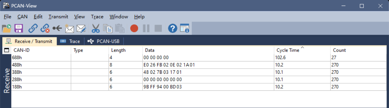
Configuration Commands (SDO)
CANopen expedited SDO is used. The host sends CAN_ID=0x600+ID, and the slave responds with CAN_ID=0x580+ID. The SDO data area is a fixed 8 bytes:
CS | Index_L | Index_H | SubIndex | Data0 | Data1 | Data2 | Data3Both Index and Data are little-endian. Common CS values are as follows:
| CS | Direction | Meaning | Data bytes |
|---|---|---|---|
| 0x23 | Host→Slave | Write 4 bytes | 4 |
| 0x2B | Host→Slave | Write 2 bytes | 2 |
| 0x2F | Host→Slave | Write 1 byte | 1 |
| 0x40 | Host→Slave | Read request | 0 |
| 0x60 | Slave→Host | Write success response | 0 |
| 0x43 | Slave→Host | Read 4-byte response | 4 |
| 0x4B | Slave→Host | Read 2-byte response | 2 |
| 0x4F | Slave→Host | Read 1-byte response | 1 |
| 0x80 | Slave→Host | SDO abort | 4-byte abort code |
This product configures common public parameters through manufacturer object indices. The table below lists only the public objects defined in this manual; unlisted objects are not a general user interface—do not derive or access them via manufacturer object indices that are not listed. Multi-byte values are arranged in little-endian when written or read. If the device denies access, it returns a 0x80 abort response; common abort codes are 0x06090030 (value out of range) and 0x06010000 (access not supported).
Common commands (using node ID=8, CAN_ID=0x608 as an example):
| Operation | Data |
|---|---|
| Modify node ID (0x209C, recommended 1–126; 127 is reserved on some models) | 23 9C 20 00 [ID] 00 00 00 |
| Save all parameters to flash (0x2000) | 23 00 20 00 00 00 00 00 |
| Reset (0x2000) | 23 00 20 00 FF 00 00 00 |
| Restore factory defaults (0x2000) | 23 00 20 00 01 00 00 00 |
| CAN baud rate 1000K (0x209A) | 23 9A 20 00 00 00 00 00 |
| CAN baud rate 800K | 23 9A 20 00 01 00 00 00 |
| CAN baud rate 500K | 23 9A 20 00 02 00 00 00 |
| CAN baud rate 250K | 23 9A 20 00 03 00 00 00 |
| CAN baud rate 125K | 23 9A 20 00 04 00 00 00 |
| Attitude relative zero (0x20A5) | 23 A5 20 00 02 00 00 00 |
| Auto-level | 23 A5 20 00 03 00 00 00 |
| Cancel leveling / restore absolute angles | 23 A5 20 00 05 00 00 00 |
| Read node ID (0x209C) | 40 9C 20 00 00 00 00 00 |
Note: CANopen parameter persistence: The TPDO period (0x180x.5) and heartbeat (0x1017) take effect immediately after being written; the CAN baud rate (0x209A) and node ID (0x209C) take effect only after a reset (write
0xFFto 0x2000), and after reset the host must also switch to the new baud rate / new node ID. For compatibility across firmware versions, after configuration it is recommended to write0x00to 0x2000 to save all parameters to flash.
Warning: After restoring factory defaults, the module automatically saves and resets; use with caution.
TPDO Rate and Synchronization Configuration
TPDO channels map to parameter indices:
| Channel | Parameter index | Data |
|---|---|---|
| TPDO1 | 0x1800 | Acceleration |
| TPDO2 | 0x1801 | Angular rate |
| TPDO3 | 0x1802 | Euler angles |
| TPDO4 | 0x1803 | Quaternion |
| TPDO6 | 0x1804 | Pressure |
| TPDO7 | 0x1805 | Inclinometer |
TPDO5 is unused; to remain compatible with existing product definitions, pressure uses TPDO6 and the inclinometer uses TPDO7.
Modify output rate (write sub-index 5, unit ms; 0=off), using acceleration (0x1800) as an example:
2B 00 18 05 00 00 00 00— off (period=0)2B 00 18 05 05 00 00 00— 200 Hz (period=5 ms)2B 00 18 05 0A 00 00 00— 100 Hz (period=10 ms)2B 00 18 05 14 00 00 00— 50 Hz (period=20 ms)2B 00 18 05 32 00 00 00— 20 Hz (period=50 ms)2B 00 18 05 64 00 00 00— 10 Hz (period=100 ms)
For the other channels, change the low byte of the index (the 2nd byte of the frame) to 01 (angular rate) / 02 (Euler angles) / 03 (quaternion) / 04 (pressure) / 05 (inclinometer); for example, angular rate at 100 Hz: 2B 01 18 05 0A 00 00 00. This item (rate, sub-index 5) takes effect immediately after being written and is automatically persisted (retained across power loss), with no extra save needed.
Synchronous mode: Writing a TPDO's transmission type [0x180x.2] as 0x01 switches it to synchronous mode (stops asynchronous timing and waits for the sync frame). Using TPDO1 as an example:
2F 00 18 02 01 00 00 00— set TPDO1 to synchronous mode2F 00 18 02 FF 00 00 00— restore TPDO1 to asynchronous mode (default)
Send a CANopen sync frame: CAN_ID=0x80, empty data. All TPDOs in synchronous mode each send one frame, achieving synchronization.
Note: The transmission type (synchronous / asynchronous) is a runtime-only setting and reverts to the asynchronous default (
0xFF) after reset or power cycle; it is not retained across power loss. The TPDO rate (sub-index 5) and heartbeat period, however, are retained across power loss.
Heartbeat: Write [0x1017.0] to set the period (ms, 0 disables). Example 2B 17 10 00 64 00 00 00 → 100 ms.
Appendix A — Quaternion / Euler Angles / Rotation Matrix Conversions
This appendix presents the attitude representations adopted by HiPNUC products and the formulas for converting between them. The quaternion order is WXYZ (
Note: Frame convention: The module's world frame defaults to East-North-Up (ENU) and can be configured to North-West-Up (NWU) (
CONFIG IMU COORD, see "Coordinate Frames and Orientation Conventions"). The section "East-North-Up (ENU) — 312 rotation order" below gives the ENU conversion formulas (consistent with the module's default output); the section "North-East-Down (NED) — 321 rotation order" gives the NED external-conversion reference commonly used in engineering practice — NED is not a device output configuration defined in this manual. The Euler angles output in NWU use the same 321 axis convention as NED (roll about X, pitch about Y, yaw about Z); only the axis directions differ (NWU: X North / Y West / Z Up). Its Euler convention differs from that of ENU (which is 312): the two have opposite axes for roll/pitch, and their yaw difference is not a constant 90°, so you cannot simply add 90° of yaw to the ENU Euler angles to obtain NWU. To convert, first rotate by 90° about the up axis at the quaternion level, then extract the Euler angles using the 321 order.
Quaternion to Rotation Matrix
Given the quaternion
East-North-Up (ENU) — 312 rotation order (Z first, then X, then Y)
Euler angle definitions under the ENU convention:
- pitch (θ): rotation angle about the X axis, range
- roll (φ): rotation angle about the Y axis, range
- yaw (ψ): rotation angle about the Z axis, range
Quaternion to Euler angles:
Euler angles to quaternion (let
North-East-Down (NED) — 321 rotation order (Z first, then Y, then X)
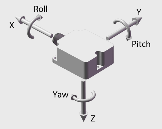
Euler angle definitions under the NED convention:
- pitch (θ): rotation angle about the Y axis, range
- roll (φ): rotation angle about the X axis, range
- yaw (ψ): rotation angle about the Z axis, range
Quaternion to Euler angles:
Euler angles to quaternion (let
Appendix B — Firmware Upgrade
This product supports firmware upgrade. Please use the CHCenter host software and follow the steps shown below; to obtain the firmware upgrade file (.hex), contact technical support.
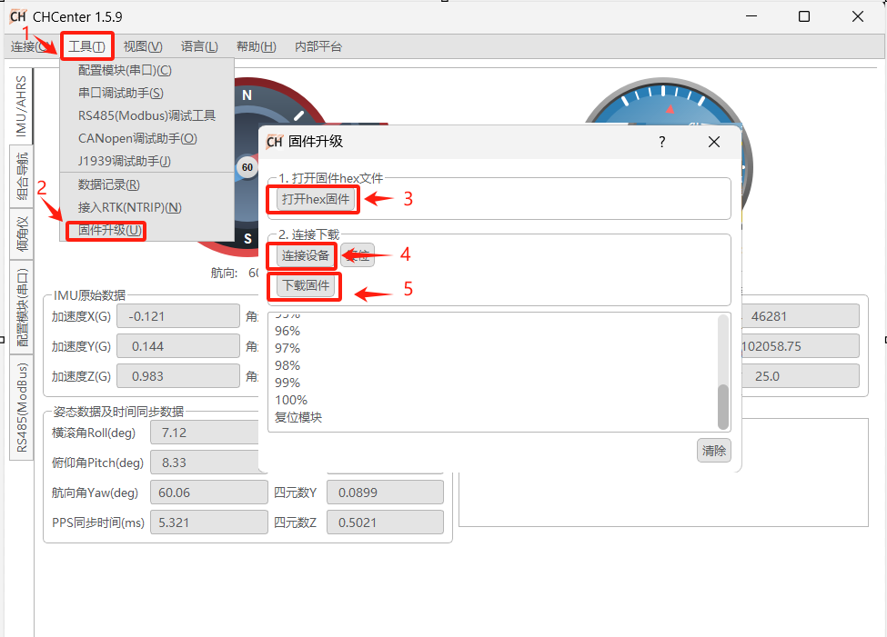
Note: Before upgrading, confirm that the firmware version matches the product model (see the version cross-reference table in "About This Manual"). Do not power off during the upgrade.
Appendix C — Output Bandwidth and Baud Rate
Whether a data frame can be output stably depends on whether frame length × frame rate stays within the serial bandwidth. Estimating with 8N1 (10 bit per byte):
In practice, it is recommended to reserve an additional 10–20% margin on top of the formula above. An HI91 frame is 82 bytes total (6 bytes of header/length/CRC + 76-byte payload); the recommended maximum output frame rate at each baud rate:
| Protocol | Bytes per frame | 9600 | 115200 | 230400 | 460800 | 921600 |
|---|---|---|---|---|---|---|
| HI91 | 82 | 10 Hz | 100 Hz | 250 Hz | 500 Hz | 1000 Hz |
Note: HI83 uses variable-length frames: its bytes per frame vary with the
data_bitmapconfiguration. Sum the frame length according to the selected fields and substitute it into the formula above for estimation. For example, with the default0x000000FF(bit0–7), a frame is about 98 bytes (payload 92 + 6 bytes of header/length/CRC); 100 Hz requires about 98 kbit/s, for which115200leaves a tight margin and230400or higher is recommended. When a high frame rate conflicts with the default115200bandwidth, raise the baud rate (e.g.921600).
Appendix D — Factory Default Configuration
The table below lists the default configuration after factory delivery or restore factory defaults (FRESET) (based on firmware 1.7.2; the actual delivered configuration prevails). The "Effective Timing" column explains when a change takes effect after modification.
| Configuration Item | Default Value | Available Range | Effective Timing |
|---|---|---|---|
| Serial baud rate (COM1–4) | 115200 | 4800…921600 (9 steps, see "System Commands") | Immediately (SERIALCONFIG) |
| Default output frame | HI91 @ 100 Hz (COM1, COM2) | — | Immediately (LOG) |
| Other frames (HI83, etc.) | Off | — | Immediately |
| Operating mode | See product delivery (6-axis / 9-axis) | CONFIG ATT MODE | Saved on write; loaded after reset / power cycle |
| World frame COORD | ENU | ENU / NWU | Saved on write; loaded after reset / power cycle |
| Mounting orientation URFR | 24 (horizontal, Z up) | See "Mounting Orientation" | Immediately (CONFIG IMU URFR) |
| HI83 data_bitmap | 0x000000FF | See "Variable-Type Data Frame (HI83)" | Saved on write; loaded after reset / power cycle |
| Modbus node ID | 80 | 1–247 | Immediately |
| CAN node ID | 8 | Recommended 1–126; 127 reserved on some models | Saved on write; reset / power cycle |
| CAN nominal baud rate | 500 kbit/s for standard firmware | 125K…1000K | Saved on write; reset / power cycle |
| J1939 periodic output master switch | On | 0 / 1 | Immediately |
| J1939 default output PGN | Acceleration / angular rate / pitch-roll / heading @ 100 Hz | See "J1939 Configuration Protocol" | Immediately |
| CANopen TPDO period | All 0 (no output) | See "TPDO Rate and Synchronization Configuration" | Immediately |
| CANopen heartbeat | Off (0) | 0–65535 ms | Immediately |
Warning: FRESET side effects: Restoring factory defaults resets the above user configuration; do not rely on FRESET to retain any user-written parameters. See
FRESETin "System Commands" for details.
Appendix E — Acronyms and Glossary
The abbreviations and technical terms used in this manual are summarized below (for command keywords such as LOG, CONFIG, SAVECONFIG, and FRESET, see "ASCII Command Reference").
| Abbreviation / Term | Full name / Meaning |
|---|---|
| IMU | Inertial Measurement Unit (accelerometer + gyroscope, optionally with magnetometer) |
| AHRS | Attitude and Heading Reference System (9-axis, absolute heading) |
| VRU | Vertical Reference Unit (6-axis, relative heading) |
| ENU / NWU / NED | East-North-Up / North-West-Up / North-East-Down; ENU/NWU are device configurations, NED is an external conversion reference (see "Coordinate Frames and Orientation Conventions", Appendix A) |
| URFR | Mounting orientation code, the axis mapping of the user frame relative to the sensor frame (see "Mounting Orientation") |
| COORD | World frame configuration (ENU / NWU, see "Coordinate Frames and Orientation Conventions", "CONFIG Configuration Commands") |
| MAIN_STATUS | Main status word, 16-bit (see "MAIN_STATUS Status Word") |
| MCAL | Magnetometer Calibration (see "Magnetic Calibration and Magnetic Environment") |
| USRCAL | User-level gyroscope calibration, calibrates the gyroscope Z-axis scale factor (see "Attitude Calibration") |
| PMUX | Pin Multiplexing, multi-function IO multiplexing (see "Multi-function IO Multiplexing") |
| SOUT | Sync Output, pre-frame sync output pulse (see "SOUT Synchronous Output") |
| SYNC_IN / PPS | Sync pulse input / standard pulse-per-second, used for triggering and time synchronization (see "Synchronization Function") |
| HI91 / HI83 | HiPNUC binary data frame types: fixed-length floating-point / variable-length bitmap |
| SOF | Start of Frame, start-of-frame sync word (5A A5) |
| CRC | Cyclic Redundancy Check |
| PGN | Parameter Group Number (J1939) |
| SA / DA | Source / Destination Address (J1939) |
| TPDO | Transmit PDO, Transmit Process Data Object (CANopen cyclic output) |
| SDO | Service Data Object (CANopen configuration read/write) |
| DBC | CAN database file, describing CAN signal definitions, for import into CANoe / BusMaster, etc. (see Appendix "Development Resources and Technical Support") |
| EDS | Electronic Data Sheet, CANopen Electronic Data Sheet (object dictionary description file, see Appendix "Development Resources and Technical Support") |
| Heave / Surge / Sway | Heave / surge / sway, the three-axis periodic motion of a vessel (see "Wave Compensation / MRU Output") |
Appendix F — Development Resources and Technical Support
The following tools and resources are available for secondary development:
| Resource | Purpose | Where to Get It |
|---|---|---|
| CHCenter host software | Device connection, parameter configuration, data plotting / attitude visualization, data recording and playback, firmware upgrade | www.hipnuc.com |
| Binary parsing example | C-language frame parsing: frame reception, CRC check, field-table decoding | See "C-Language Parsing Example (HI91)" |
| Firmware upgrade | Upgrade via CHCenter; contact technical support for the .hex file | See Appendix B |
| DBC / EDS (CAN) | J1939 DBC and CANopen EDS machine-readable files for import into CANoe / BusMaster / PLC | Contact technical support |
Information about new products and resources is available on the official website and WeChat official account.
Website: www.hipnuc.com
WeChat official account:

Telegram: