
HiPNUC GNSS/INS Command and Programming Manual
Rev 2.0
For HiPNUC GNSS/INS integrated navigation products
Version and Scope
This manual primarily covers the current HiPNUC HIxxN GNSS/INS product range. Physical interfaces and optional features vary by model; refer to the product datasheet and delivered configuration. Commands, registers and some data fields described here may not apply to legacy HI32 products; use the documentation applicable to the delivered device.
When first connecting or troubleshooting, use LOG VERSION to query the product name and firmware version.
| Interface | Data and protocols | Applicability |
|---|---|---|
| Serial (RS-232 or RS-422) | HI81, GGA, RMC, RTCM3, ASCII configuration commands | Electrical levels and port count depend on the model |
| Ethernet | HI81, GGA, RMC, ASCII configuration commands | Models equipped with Ethernet only |
| CAN | SAE J1939 | Configurable CAN baud rate and node address |
| PPS/SYNC | PPS output | Refer to the model-specific datasheet for pins, levels and timing |
Quick Start
Connect COM1
- Check power, COM1 electrical interface, wiring and antenna connections against the product datasheet.
- Configure the receiver for
115200 bps, 8N1: 8 data bits, no parity, 1 stop bit. - Receive COM1 data after power-up. Default output is HI81 binary data at
0.01 sintervals (100 Hz).
Verify HI81 Data
Search for frame header 0x5A 0xA5, extract the complete frame using the payload length, and verify its CRC. Communication is established when:
- Frames with correct CRCs arrive continuously;
- The payload contains HI81 data with tag
0x81; - The frame period is approximately 10 ms.
An ins_status that has not entered integrated navigation does not mean communication failed. After verifying communication, use the HI81 definition and status guidance below to check installation, antennas, GNSS positioning and navigation status.
Use Other Protocols
Configure GGA, RMC, RTCM3 and J1939 as required by the application. Commands, fields and verification methods are given in their protocol sections; the quick-start procedure does not change default output settings.
Document Revision History
| Version | Date | Author | Changes |
|---|---|---|---|
| V2.0 | Sep 13, 2026 | HiPNUC | Restructured scope, quick start, correction data and protocol guidance |
| V1.0 | Oct 1, 2023 | HiPNUC | Initial version |
Installation and Coordinate Frames
Body Frame
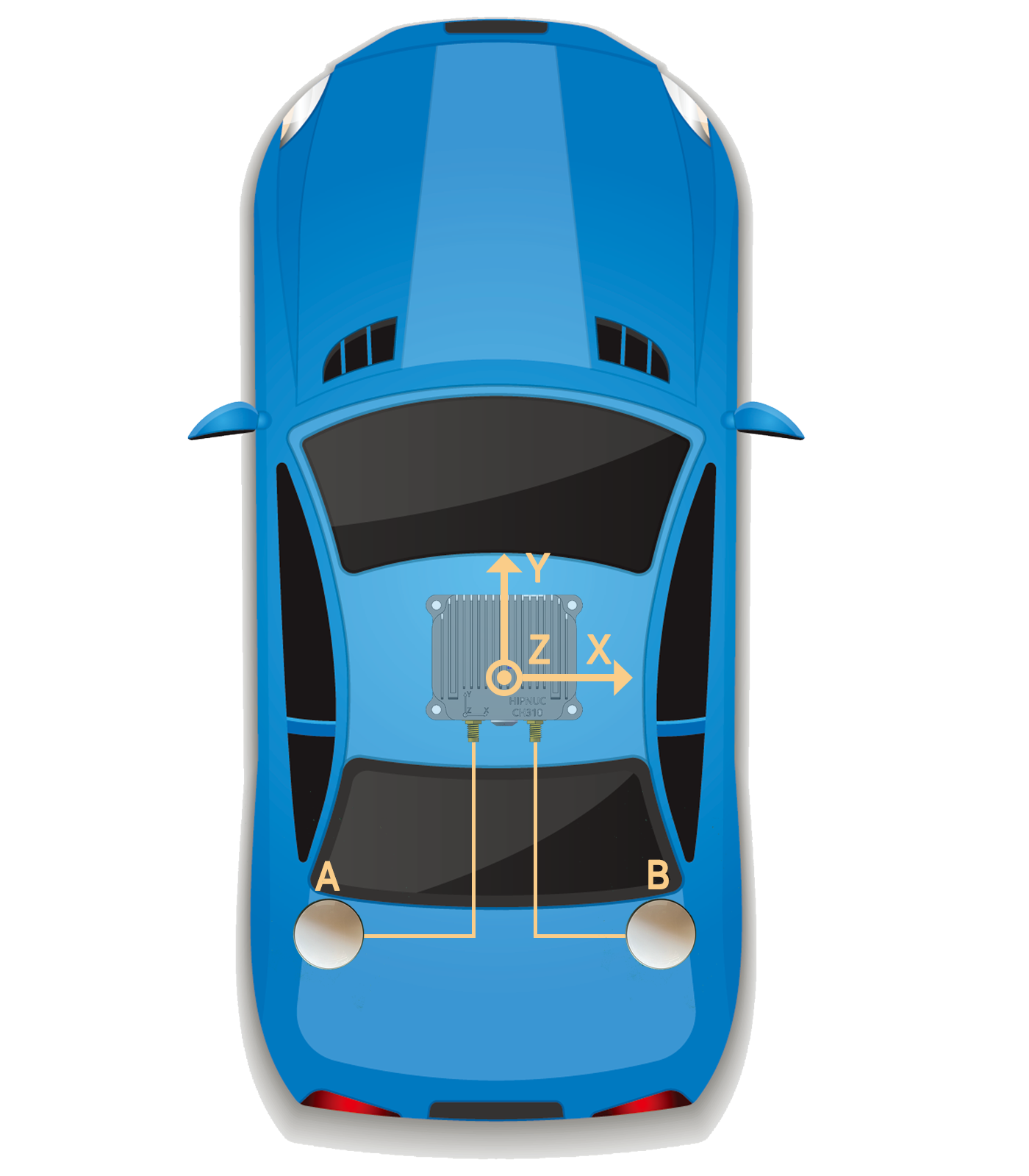
The device body frame (b-frame) is right-handed: Y points forward along the vehicle, X right and Z up. With the default mounting, the b-frame matches the X / Y / Z markings on the enclosure; for other horizontal mountings, declare where the enclosure arrows point on the vehicle with the mounting code below, and the device aligns its output to the vehicle accordingly.
The device, antennas and vehicle must be rigidly fixed together; relative positions and orientations must not change during operation. Measure lever arms to the antenna phase centers.
HI81 fields ins_lon, ins_lat and ins_msl give the integrated-navigation position of the IMU origin. See the individual GGA and RMC descriptions for their position sources.
Navigation Frame
In integrated-navigation operating modes the navigation frame is fixed at East-North-Up (ENU): X east, Y north, Z up. vel_enu and acc_enu use east, north, up order. Heading is zero at true north and positive clockwise. The output data axes are fixed at Right-Front-Up: CONFIG IMU COORD accepts only 0, and LOG USRCONFIG reads back COORD=0.
ENU Euler angles use the 3-1-2 (Z-X-Y) rotation order: heading, pitch, then roll. The quaternion represents body-to-navigation rotation in W, X, Y, Z order.
Horizontal Mounting Orientation (HIxxN)
For horizontal HIxxN installations, CONFIG IMU URFR <CODE> declares where the X and Y arrows printed on the enclosure point on the vehicle; the Z arrow stays up. Directions are the vehicle's: front is where it drives, right is the driver's right-hand side.
| Code | X arrow points | Y arrow points |
|---|---|---|
24 | Right (default) | Front |
304 | Front | Left |
214 | Back | Right |
134 | Left | Back |
Save, reboot and read back:
CONFIG IMU URFR 24
SAVECONFIG
REBOOT
LOG USRCONFIG
Dual-Antenna Baseline and Lever Arms
A is the primary positioning antenna and B is the dual-antenna heading antenna. Do not interchange connectors or ANTA and ANTB coordinates. These are the position vectors from the IMU origin to the phase centers of antennas A and B, respectively, in the device body frame (the vehicle's right, front and up after the mounting correction: X right, Y front, Z up) and in meters. The baseline vector is ANTB - ANTA.
Set antenna A's lever arm:
SETBASELINE ANTA <X,Y,Z>
Set antenna B's lever arm:
SETBASELINE ANTB <X,Y,Z>
Separate parameters with commas, without spaces. Each antenna lever-arm length must not exceed 1000 m; baseline length must be 0.05–1000 m.
For example, A and B at (-1.5, -1.2, -0.3) and (1.5, -1.2, -0.3) relative to the IMU:
SETBASELINE ANTA -1.5,-1.2,-0.3
SETBASELINE ANTB 1.5,-1.2,-0.3
SAVECONFIG
REBOOT
After rebooting, send LOG INSCONFIG and check ANTA and ANTB against the actual installation. Accurate lever arms reduce errors caused by different antenna and IMU positions during vehicle rotation.
The lever arms can also be read and written as registers: ANTA X / Y / Z at 0x03D0 / 0x03D2 / 0x03D4 and ANTB at 0x03D6 / 0x03D8 / 0x03DA, each value the 32-bit pattern of an IEEE-754 single-precision float, in meters. Over J1939, write them one at a time as in Configure J1939; they take effect after saving and rebooting. A value whose magnitude exceeds 1000 m is rejected; writing one value at a time does not check the spacing between the antennas, so the host should confirm it is at least 0.05 m before writing. The "Installation" page of the CHCenter configuration dialog reads and writes the lever arms directly.
Common Operations
Configuration uses ASCII commands. End every command with carriage return and line feed \r\n. Success normally returns OK; ERR or text beginning with ERROR indicates failure. When communication settings change, the device reboots or a timeout occurs, use readback and valid data as final verification.
Command Overview
| Command | Purpose |
|---|---|
REBOOT | Reboot the device |
LOG | Query information or control a specified serial port's output |
CONFIG | Configure navigation operating parameters |
UNLOGALL | Disable all periodic messages on the current serial port |
SAVECONFIG | Save configuration that must survive power loss |
FRESET | Restore default user configuration |
SETBASELINE | Set A and B antenna lever arms |
SERIALCONFIG | Set a specified serial port's baud rate |
LOG and SERIALCONFIG accept a target port after the command, for example LOG COM2 COMCONFIG or SERIALCONFIG COM2 460800. Without COMx, they apply to the port receiving the command. Available ports depend on the model.
Reboot
REBOOT immediately restarts the device, equivalent to cycling power. Run SAVECONFIG first for parameters that must be retained.
Query and Control Serial Output
Pause or Resume Output
LOG ENABLE: resume output on the port receiving the command;LOG DISABLE: pause output on the port receiving the command.
These commands only control that port's runtime output and do not change other serial-port settings.
Query Version
LOG VERSION queries product name and firmware version. PNAME, APP_VER and BL_VER identify the product name, application firmware version and Bootloader version. Responses may include serial number, build date and other information; do not assume a fixed field or line count.
Query Serial Configuration
LOG [COMx] COMCONFIG queries baud rate and message periods on the current or specified port. Returned ONTIME values are milliseconds:
COM=COM1
BAUD=115200
MSG=HI81, ONTIME=10
The device may also list other messages supported by that port.
Query Dual-Antenna Configuration
LOG INSCONFIG queries A and B antenna lever arms. Principal fields:
ANTA=0.000,0.000,0.200
ANTB=0.000,1.000,0.200
Additional fields may be returned; do not assume a fixed field or line count.
Configure Periodic Messages
Syntax: LOG [COMx] <MSG> ONTIME <PERIOD>.
| Parameter | Description |
|---|---|
MSG | HI81, GGA or RMC |
PERIOD | Period in seconds; common supported range 0–32.767 s; 0 disables the message |
Example:
LOG HI81 ONTIME 0.01
SAVECONFIG
This sets the current port's HI81 period to 10 ms (100 Hz). GGA and RMC commonly use 0.1 or 1 second. Calculate the combined bandwidth required by all enabled messages, including serial framing, and leave headroom below the port's baud rate. OK means the configuration was accepted; it does not guarantee the actual output period. Periodic messages may be skipped when bandwidth is insufficient or transmission is congested.
Configure the Navigation Operating Mode
Syntax: CONFIG MODEL <MODEL>.
MODEL | Description |
|---|---|
CAR | Vehicle mode with vehicle motion constraints; factory default |
SHIP | Marine mode |
PLANE | Aircraft mode without vehicle motion constraints |
Save and reboot:
CONFIG MODEL CAR
SAVECONFIG
REBOOT
Configure NTRIP
Only models with a supported network interface or associated DTU can use NTRIP directly. Refer to the product datasheet and delivered configuration for wiring, network access and associated equipment.
CONFIG NTRIP <SERVER> <PORT> <MOUNTPOINT> <USERNAME> <PASSWORD>| Parameter | Description |
|---|---|
SERVER | CORS/NTRIP service domain name or IP address |
PORT | Service port |
MOUNTPOINT | Mountpoint |
USERNAME | Account username |
PASSWORD | Account password |
Credential Security
LOG NTRIPCONFIG may return usernames and passwords. Remove credentials before saving terminal logs, taking screenshots or requesting technical support.
The address and account below illustrate syntax only:
CONFIG NTRIP caster.example.com 2101 MOUNT1 demo_user demo_password
SAVECONFIG
REBOOT
After rebooting, read back server, port, mountpoint and account settings with LOG NTRIPCONFIG. Check HI81 GNSS positioning status to confirm RTK. Acquisition time depends on antenna environment, correction service, network quality and base-station distance.
Disable All Periodic Messages on the Current Port
UNLOGALL disables all periodic messages on the port receiving the command, including default HI81 output. Other ports are unaffected. Run SAVECONFIG afterward if the change must survive power loss.
Save Configuration
Run SAVECONFIG after changes that must be retained. Run REBOOT afterward only for settings explicitly documented as requiring a reboot.
Restore Defaults
Record Settings Before Restoring
FRESET overwrites user configuration with defaults. Record required lever arms, network, output and bus settings first; redact NTRIP credentials in terminal logs.
Use FRESET only for configuration problems unresolved by ordinary troubleshooting:
- Record required settings, then send
FRESET. - Wait for restart; cycle power if communication does not return.
- Reconnect to COM1 at
115200 bps, 8N1and verify continuous 100 Hz HI81 output. - Read back configuration, restore application settings, and verify navigation and communication data again.
If some settings are not back at their defaults after the restart (for example, no HI81 output), do not send FRESET again: set the missing items by hand as in step 4 (for example, LOG HI81 ONTIME 0.01), then run SAVECONFIG.
Change the Serial Baud Rate
Supported values are 115200, 460800 and 921600:
SERIALCONFIG [COMx] <BAUD>- Send
LOG [COMx] COMCONFIGto record the target port's current settings. - Send
SERIALCONFIG [COMx] <BAUD>. If changing the port receiving the command, switch the host to the new rate after receivingOK. - Send
SAVECONFIGthrough a port that still communicates. - Read
LOG [COMx] COMCONFIGto checkBAUDagainst the target; verify valid data on that port.
Serial and Network Protocols
Introduction
Serial ports and applicable network interfaces carry NMEA 0183 ASCII and HiPNUC binary messages. Both may share one port; identify their start markers separately as $ and 0x5A 0xA5.
Transport Interfaces
- RS-232 and RS-422 use the same serial format. Device and receiver baud rates must match; the default is 115200 bps.
- Some models have Ethernet and obtain an IP address through DHCP. The default connection uses TCP port 5944. Once connected, command and data formats match the serial interface. Network capabilities depend on the datasheet and delivered configuration.
NMEA Messages (ASCII)
NMEA messages start with $, end with * and a two-digit hexadecimal checksum, then carriage return and line feed 0x0D 0x0A:
$<Talker><Type>,<Field1>,<Field2>,...*<Checksum><CR><LF>| Field | Description |
|---|---|
$ | Start character, ASCII 0x24 |
Talker | Two-character identifier; current products default to GP. Identify data by message type without restricting the satellite system based on this identifier |
Type | Three-character type; this manual documents GGA and RMC |
, | Separator, ASCII 0x2C; retain separators for empty fields |
* | Separates data and checksum |
Checksum | Bytewise XOR of all characters between $ and *, as two uppercase hexadecimal ASCII characters |
<CR><LF> | Terminator, ASCII 0x0D 0x0A |
NMEA Message List
| Message | Description | Data source |
|---|---|---|
| GGA | Position, UTC time, fix quality and satellites used | Position solution |
| RMC | Time, position, ground speed and course over ground | Position and velocity solution |
GGA and RMC position sources vary by product implementation: GNSS antenna position or integrated-navigation result. For consistent integrated position, velocity and attitude referenced to the IMU origin, parse HI81.
When external time changes, time fields may temporarily be invalid. Check validity continuously and confirm the new epoch before using absolute time.
GGA
Receiver time, position and positioning-related data.
Treat the fix as invalid if quality is empty or 0; do not rely on fixed placeholder values in other fields. Empty time means invalid UTC. The sentence may still output at its configured period.
$GPGGA,062134.00,2813.9908005,N,11252.6285300,E,1,28,0.5,83.684,M,-17.038,M,0.0,0000*54| ID | Example | Format | Description |
|---|---|---|---|
| 1 | $GPGGA | Header | |
| 2 | 062134.00 | hhmmss.ss | UTC time |
| 3 | 2813.9908005 | ddmm.m… | Latitude: first two digits degrees, remainder minutes; 0°–90° |
| 4 | N | - | Latitude direction: N north, S south |
| 5 | 11252.6285300 | dddmm.m… | Longitude: first three digits degrees, remainder minutes; 0°–180° |
| 6 | E | - | Longitude direction: E east, W west |
| 7 | 1 | x | 0 invalid; 1 single-point or PPP; 2 pseudorange differential; 4 RTK fixed; 5 RTK float |
| 8 | 28 | xx | Satellites used for positioning |
| 9 | 0.5 | x.x | HDOP: horizontal dilution of precision |
| 10 | 83.684 | x.xxx | Altitude above mean sea level |
| 11 | M | U | Altitude unit: m |
| 12 | -17.038 | x.xxx | Geoid undulation: WGS84 ellipsoidal height minus altitude above mean sea level |
| 13 | M | U | Geoid undulation unit: m |
| 14 | 0.0 | x.x | Differential age in s |
| 15 | 0000 | xxxx | Differential station ID |
| 16 | 54 | hh | Checksum |
Latitude and longitude use degrees and minutes, without a separate seconds field. Convert with
decimal degrees = degrees + minutes / 60, then apply the sign from N/S/E/W. Decimal precision may vary by firmware; parse comma-separated decimal values, not fixed-width slices.
RMC
Recommended minimum navigation data.
Treat the fix as invalid if positioning status is empty or V; do not rely on fixed placeholder values for position, speed or course. Empty time or date means invalid UTC. The sentence may still output at its configured period.
$GPRMC,020550.00,A,2813.9891299,N,11252.6278784,E,0.03,315.70,161117,0.0,E,A,V*49| ID | Example | Format | Description |
|---|---|---|---|
| 1 | $GPRMC | Header | Start character and message type |
| 2 | 020550.00 | hhmmss.ss | UTC time |
| 3 | A | x.x | Positioning status: A valid, V invalid |
| 4 | 2813.9891299 | ddmm.m… | Latitude format as in GGA |
| 5 | N | - | Latitude direction as in GGA |
| 6 | 11252.6278784 | dddmm.m… | Longitude format as in GGA |
| 7 | E | - | Longitude direction as in GGA |
| 8 | 0.03 | x.xx | Horizontal ground speed in knots |
| 9 | 315.70 | x.xx | Course over ground, true-north reference, positive clockwise, 0°–360° |
| 10 | 161117 | ddmmyy | Date: day, month, year |
| 11 | 0.0 | x.x | Reserved; ignore |
| 12 | E | - | Reserved; ignore |
| 13 | A | - | Mode: N invalid; A autonomous; D differential; E estimated; F RTK float; R RTK fixed |
| 14 | V | - | Extended status; do not use alone to determine fix validity |
| 15 | 49 | hh | Checksum |
Determine RMC fix validity primarily from field 3 (A/V), together with field 13's mode. Field 14 is not an independent indication of validity.
HiPNUC Binary Messages
HI81 is the common binary output for HiPNUC GNSS/INS products. Serial format is 8N1; physical interfaces depend on the datasheet.
Unless stated otherwise, integer fields' physical values equal raw values multiplied by scale factors.
Frame Format
COM1 defaults to 100 Hz HI81. Multi-byte integers and CRC are little-endian.
| Frame order | Value | Length (bytes) | Description |
|---|---|---|---|
| Sync byte 1 | 0x5A | 1 | Fixed |
| Sync byte 2 | 0xA5 | 1 | Fixed |
| Payload length | 0x0068 for HI81 | 2 | Payload only, excluding sync, length and CRC |
| CRC | - | 2 | Little-endian; skip this field during calculation |
| Payload | First byte 0x81 | 104 for HI81 | Fields below |
A complete HI81 frame is 110 bytes: CRC at frame offsets 4–5, payload from offset 6. Table offsets below start at the first payload byte, 0x81.
Payload Content
Integrated Navigation Data (HI81)
HI81 payload length is fixed at 104 bytes.
Integrated Navigation Status
ins_status is the common field identifying the navigation operating phase:
| Value | State | Meaning |
|---|---|---|
| 0 | Invalid | Information required for initialization not yet obtained |
| 1 | Aligning | Initialization started, but integrated navigation not yet active |
| 3 | Integrated navigation | Initialized with valid GNSS aiding |
| 6 | Inertial dead reckoning | Initialized, but GNSS aiding currently unavailable; propagating inertially |
| Offset | Name | Type | Size (bytes) | Unit | Scale | Description |
|---|---|---|---|---|---|---|
| 0 | tag | uint8_t | 1 | - | - | Packet tag: 0x81 |
| 1 | status | uint16_t | 2 | - | - | Reserved; do not interpret |
| 3 | ins_status | uint8_t | 1 | - | - | Navigation status as above |
| 4 | gpst_wn | uint16_t | 2 | week | 1 | GPS week |
| 6 | gpst_tow | uint32_t | 4 | s | 0.001 | GPS time of week |
| 10 | reserved | uint8_t[2] | 2 | - | - | Reserved; ignore |
| 12 | gyr_b | int16_t[3] | 6 | rad/s | 0.001 | Body X, Y, Z angular rate; factory-calibrated IMU measurements |
| 18 | acc_b | int16_t[3] | 6 | m/s² | 0.0048828 | Body X, Y, Z acceleration; factory-calibrated IMU measurements |
| 24 | mag_b | int16_t[3] | 6 | μT | 0.030517 | Body X, Y, Z magnetic field; factory-calibrated IMU measurements |
| 30 | air_pressure | int16_t | 2 | Pa | 1 | Actual pressure = field value + 100000 Pa; 2000 means 102000 Pa |
| 32 | reserved | uint8_t[2] | 2 | - | - | Reserved; ignore |
| 34 | temperature | int8_t | 1 | °C | 1 | Temperature |
| 35 | utc_year | uint8_t | 1 | year | 1 | UTC year minus 2000; 24 means 2024 |
| 36 | utc_month | uint8_t | 1 | month | 1 | UTC month |
| 37 | utc_day | uint8_t | 1 | day | 1 | UTC day |
| 38 | utc_hour | uint8_t | 1 | h | 1 | UTC hour |
| 39 | utc_min | uint8_t | 1 | min | 1 | UTC minute |
| 40 | utc_msec | uint16_t | 2 | s | 0.001 | UTC seconds and milliseconds |
| 42 | roll | int16_t | 2 | deg | 0.01 | Roll, -180°–180° |
| 44 | pitch | int16_t | 2 | deg | 0.01 | Pitch, -90°–90° |
| 46 | yaw | uint16_t | 2 | deg | 0.01 | Heading, zero at true north, positive clockwise, 0°–360° |
| 48 | quat | int16_t[4] | 8 | - | 0.0001 | Body-to-navigation quaternion, W, X, Y, Z |
| 56 | ins_lon | int32_t | 4 | deg | 1e-7 | Integrated-navigation longitude |
| 60 | ins_lat | int32_t | 4 | deg | 1e-7 | Integrated-navigation latitude |
| 64 | ins_msl | int32_t | 4 | m | 0.001 | Integrated-navigation altitude above mean sea level |
| 68 | pdop | uint8_t | 1 | - | 0.1 | GNSS position dilution of precision |
| 69 | hdop | uint8_t | 1 | - | 0.1 | GNSS horizontal dilution of precision |
| 70 | solq_pos | uint8_t | 1 | - | - | GNSS fix quality: 0 invalid; 1 single-point or PPP; 2 pseudorange differential; 4 RTK fixed; 5 RTK float |
| 71 | nv_pos | uint8_t | 1 | - | - | Satellites used for GNSS positioning |
| 72 | solq_heading | uint8_t | 1 | - | - | Dual-antenna heading quality: 4 fixed; otherwise unavailable |
| 73 | nv_heading | uint8_t | 1 | - | - | Satellites used for dual-antenna heading |
| 74 | diff_age | uint8_t | 1 | s | 1 | RTK differential age |
| 75 | undulation | int16_t | 2 | m | 0.01 | WGS84 ellipsoidal height minus altitude above mean sea level |
| 77 | reserved | uint8_t | 1 | - | - | Reserved; ignore |
| 78 | vel_enu | int16_t[3] | 6 | m/s | 0.01 | Navigation-frame east, north, up velocity |
| 84 | acc_enu | int16_t[3] | 6 | m/s² | 0.0048828 | Navigation-frame east, north, up acceleration |
| 90 | reserved | uint8_t[14] | 14 | - | - | Reserved; ignore |
Use gpst_wn, gpst_tow and UTC fields as absolute time only after obtaining a valid GNSS/UTC epoch. Do not rely on fixed placeholders for invalid time; HI81 may still output at the configured period.
Skip reserved fields by their fixed lengths; their values must not change parsing layout.
CRC
HI81 uses CRC-16/XMODEM: polynomial 0x1021, initial value 0x0000, no input/output reflection and no final XOR. It covers header, length and payload, excluding the CRC field itself.
static void crc16_update(uint16_t *currentCrc, const uint8_t *src,
                         uint32_t lengthInBytes)
{
    uint32_t crc = *currentCrc;
    for (uint32_t j = 0; j < lengthInBytes; ++j)
    {
        crc ^= (uint32_t)src[j] << 8;
        for (uint32_t i = 0; i < 8; ++i)
        {
            uint32_t temp = crc << 1;
            if (crc & 0x8000)
                temp ^= 0x1021;
            crc = temp;
        }
    }
    *currentCrc = (uint16_t)crc;
}

uint16_t crc = 0;
crc16_update(&crc, frame, 4);       /* 5A A5 LEN_L LEN_H */
crc16_update(&crc, frame + 6, 104); /* HI81 payload */

uint16_t receivedCrc = (uint16_t)frame[4] | ((uint16_t)frame[5] << 8);
bool crcOk = (crc == receivedCrc);
RTCM3 Correction Data
RTCM3 carries GNSS corrections. Keep COM1's default HI81 output and use an available COM2 for RTCM3. Base-station output and rover correction input are separate workflows.
Rover Correction Input
Feed the correction source's raw RTCM3 bytes directly into COM2, without ASCII commands, line terminators or other wrappers. The source and COM2 baud rates must match.
Use one correction source at a time. Continuously monitor HI81: diff_age should update with corrections; solq_pos of 4 (RTK fixed) or 5 (RTK float) indicates the position solution is using RTK.
Base-Station RTCM3 Output
Record the current mode and port configuration before switching to base-station mode. On COM2, run:
UNLOGALL
CONFIG MODEL BASE
LOG RTCM3 ONTIME 1
SAVECONFIG
REBOOT
The nonzero value in LOG RTCM3 ONTIME 1 only enables RTCM3 forwarding; it does not set the RTCM generation rate. The internal GNSS module generates these messages, which the device forwards:
| RTCM3 message | Rate |
|---|---|
| 1005 | 1 Hz |
| 1074 | 1 Hz |
| 1094 | 1 Hz |
| 1124 | 1 Hz |
After reboot, verify complete RTCM3 frames with correct checksums on COM2. To return to integrated navigation, select CAR, SHIP or PLANE and restore required port outputs.
CAN Interface: SAE J1939
CAN-equipped INS products use SAE J1939, default baud rate 500 kbit/s and device address 0x08. Interface capabilities depend on the model and delivered configuration.
Positions in FF10 and FF14 refer to the IMU origin, as in HI81.
J1939 uses a 29-bit extended ID: priority P (3 bits), reserved R (1 bit), data page DP (1 bit), PDU format PF (8 bits), PDU specific PS (8 bits), source address SA (8 bits). Here measurement PGNs have PF=0xFF and are PDU2 broadcasts: PS is the PGN's low 8 bits, SA the device address.
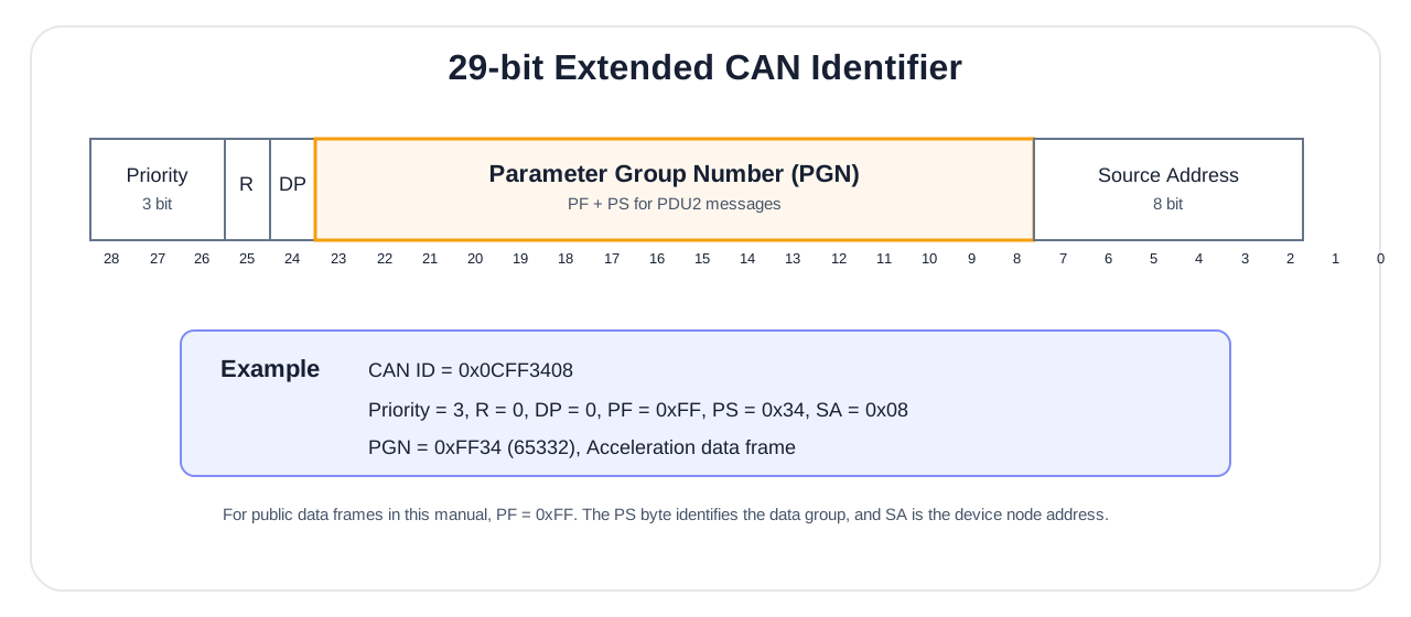
| Item | Convention |
|---|---|
| Communication mode | Periodic measurement PGN broadcasts |
| Data length | All measurement PGNs in this section are 8 bytes |
| PF | 0xFF |
| Priority | 3 |
| Default source address | 0x08 |
| Data format | Multi-byte values little-endian; signed integers unless explicitly unsigned or status fields |
Each PGN period is independently configured; defaults may vary by product. Use readback and actual received periods, not an assumed common default.
PGN Message List
PGN 65296 (FF10): Latitude and Longitude
Default-address CAN ID: 0x0CFF1008.
| SPN | Bytes | Description |
|---|---|---|
| Latitude | 0–3 | int32_t, deg, scale 1e-7 |
| Longitude | 4–7 | int32_t, deg, scale 1e-7 |
PGN 65300 (FF14): Altitude and Differential Age
Default-address CAN ID: 0x0CFF1408.
| SPN | Bytes | Description |
|---|---|---|
| Altitude above mean sea level | 0–3 | int32_t, m, scale 0.01 |
| Geoid undulation | 4–5 | int16_t, m, scale 0.01 |
| Differential age | 6–7 | int16_t, s, scale 0.01 |
PGN 65304 (FF18): Fix Status and Satellite Counts
Default-address CAN ID: 0x0CFF1808.
| SPN | Bytes | Description |
|---|---|---|
| GNSS fix quality | 0 | 0 invalid; 1 single-point or PPP; 2 pseudorange differential; 4 RTK fixed; 5 RTK float |
| Dual-antenna heading quality | 1 | 4 fixed; otherwise unavailable |
| Positioning satellites | 2 | Satellites used for GNSS positioning |
| Heading satellites | 3 | Satellites used for dual-antenna heading |
ins_status | 4 | Same navigation-status definition as HI81 |
| Reserved | 5–7 | Ignore |
PGN 65318 (FF26): Velocity
Default-address CAN ID: 0x0CFF2608.
| SPN | Bytes | Description |
|---|---|---|
| East velocity | 0–1 | int16_t, m/s, scale 0.01 |
| North velocity | 2–3 | int16_t, m/s, scale 0.01 |
| Up velocity | 4–5 | int16_t, m/s, scale 0.01 |
| Horizontal ground speed | 6–7 | int16_t, m/s, scale 0.01 |
PGN 65327 (FF2F): Time
Default-address CAN ID: 0x0CFF2F08.
| SPN | Bytes | Description |
|---|---|---|
| UTC year | 0 | Year minus 2000; 24 means 2024 |
| UTC month | 1 | |
| UTC day | 2 | |
| UTC hour | 3 | |
| UTC minute | 4 | |
| UTC second | 5 | |
| UTC milliseconds | 6–7 | uint16_t, ms, scale 1 |
Use FF2F as UTC only with a plausible, nonzero date. Ignore it until absolute time is valid; do not rely on invalid-time placeholder values.
PGN 65332 (FF34): Acceleration
Default-address CAN ID: 0x0CFF3408.
| SPN | Bytes | Description |
|---|---|---|
| Acceleration X | 0–1 | int16_t, g, scale 0.00048828 |
| Acceleration Y | 2–3 | int16_t, g, scale 0.00048828 |
| Acceleration Z | 4–5 | int16_t, g, scale 0.00048828 |
| Reserved | 6–7 | Ignore |
PGN 65335 (FF37): Angular Rate
Default-address CAN ID: 0x0CFF3708.
| SPN | Bytes | Description |
|---|---|---|
| Angular rate X | 0–1 | int16_t, deg/s, scale 0.061035 |
| Angular rate Y | 2–3 | int16_t, deg/s, scale 0.061035 |
| Angular rate Z | 4–5 | int16_t, deg/s, scale 0.061035 |
| Reserved | 6–7 | Ignore |
PGN 65341 (FF3D): Roll and Pitch
Default-address CAN ID: 0x0CFF3D08.
| SPN | Bytes | Description |
|---|---|---|
| Roll | 0–3 | int32_t, deg, scale 0.001 |
| Pitch | 4–7 | int32_t, deg, scale 0.001 |
PGN 65345 (FF41): Heading
Default-address CAN ID: 0x0CFF4108.
| SPN | Bytes | Description |
|---|---|---|
| Heading (clockwise) | 0–3 | uint32_t, zero at true north, positive clockwise, 0°–360°, deg, scale 0.001 |
| Reserved | 4–7 | Ignore |
PGN 65347 (FF43): Temperature
Default-address CAN ID: 0x0CFF4308.
| SPN | Bytes | Description |
|---|---|---|
| Temperature | 0–1 | int16_t, °C, scale 0.01 |
| Reserved | 2–7 | Ignore |
Configure J1939
Configuration uses PDU1 PGN 0xEF00, with the host fixed at source address 0x55. At default device address 0x08:
- Host request ID:
0x0CEF0855, destination device0x08, source host0x55; - Device response ID:
0x0CEF5508, destination host0x55, source device0x08.
Configuration frames are 8 bytes:
| Field | Bytes | Description |
|---|---|---|
ADDR | 0–1 | 16-bit register address, little-endian |
CMD | 2 | 0x06 write, 0x03 read |
STATUS | 3 | Reserved; host sends 0x00 |
VAL | 4–7 | 32-bit value, little-endian; send 0 for reads |
Successful ordinary writes echo the request; successful reads return the current VAL. Invalid addresses or parameters may receive no response. Set a timeout rather than waiting indefinitely.
Configuration Registers
| Address | Object | Value |
|---|---|---|
0x0110 | FF10 latitude/longitude period | 0 off; 10–1000 ms |
0x0114 | FF14 altitude/differential age period | 0 off; 10–1000 ms |
0x0118 | FF18 fix-status period | 0 off; 10–1000 ms |
0x0126 | FF26 velocity period | 0 off; 10–1000 ms |
0x012F | FF2F time period | 0 off; 10–1000 ms |
0x0134 | FF34 acceleration period | 0 off; 10–1000 ms |
0x0137 | FF37 angular-rate period | 0 off; 10–1000 ms |
0x013D | FF3D roll/pitch period | 0 off; 10–1000 ms |
0x0141 | FF41 heading period | 0 off; 10–1000 ms |
0x0143 | FF43 temperature period | 0 off; 10–1000 ms |
0x009A | CAN baud rate | 0 1000 kbit/s; 1 800 kbit/s; 2 500 kbit/s; 3 250 kbit/s; 4 125 kbit/s |
0x009C | Device address | 1–64, default 8 |
0x009D | J1939 periodic-output master switch | 0 off; 1 on |
0x03D0–0x03DA | Antenna lever arms ANTA, ANTB | One address per axis, float bit pattern, in m; see Dual-Antenna Baseline and Lever Arms; takes effect after saving and rebooting |
0x0000 | Control | 0x00000000 save; 0x000000FF reboot |
For example, set FF37 angular-rate period to 100 ms:
ID   = 0x0CEF0855
DATA = 37 01 06 00 64 00 00 00
Read 0x0137 to verify:
ID   = 0x0CEF0855
DATA = 37 01 03 00 00 00 00 00
Disable all J1939 periodic output:
ID   = 0x0CEF0855
DATA = 9D 00 06 00 00 00 00 00
Set VAL to 01 00 00 00 to re-enable. Read back the target register, then write 0x00000000 to 0x0000 to save and 0x000000FF to reboot. Verify actual CAN IDs and periods. After a baud-rate change, verify with the new rate after reboot. Reboot may occur before its response; valid messages received again with new parameters establish success.
Status and Troubleshooting
Integrated-Navigation Initialization
Working communication does not mean navigation is initialized. The device first establishes position from a valid GNSS fix, then initializes using fixed dual-antenna heading or velocity heading from sustained motion. Without dual-antenna heading, maintain steady motion under good satellite conditions and check ins_status.
Throughout initialization and operation, ins_status means: 0 invalid, 1 aligning, 3 integrated navigation, 6 inertial dead reckoning. State 6 continues outputting navigation data, but errors accumulate with outage duration and motion conditions. Integrated navigation resumes automatically when GNSS aiding is valid again.
Troubleshooting Order
| Symptom | Check first | Assessment and action |
|---|---|---|
| No HI81 on COM1 | Power, levels, TX/RX, common ground, 115200 8N1 | Verify continuous complete 110-byte frames starting 0x5A 0xA5 with correct CRC; use LOG COMCONFIG to check settings if needed |
ins_status remains 0 or 1 | Antenna A sky view, solq_pos, satellite count, mode, lever arms | Also check A/B connections, baseline direction and solq_heading=4 on dual-antenna models; without fixed heading, maintain steady motion for heading initialization |
ins_status changes 3 to 6 | solq_pos, differential age, obstructions, GNSS continuity | With NTRIP, also check network, server, mountpoint and account; observe return to 3 when valid aiding resumes |
| Incorrect heading direction or large offset | Device Y forward, A/B order, ANTA, ANTB, rigid mounting | Verify true-north zero and clockwise-positive; dual-antenna heading requires solq_heading=4 |
| RTK will not fix | Antenna conditions, corrections, diff_age, network, NTRIP | Confirm continuous correction reception, then account, base distance and obstructions; a fixed waiting time is not a success criterion |
| No J1939 messages | CAN availability, 500 kbit/s, 29-bit extended frames, termination, address, periods | Read target PGN period, then check ID against actual device address; do not assume identical defaults across firmware |
Before Contacting Technical Support
Prepare product name and APP_VER, LOG COMCONFIG, LOG INSCONFIG, and a short raw HI81 or CAN capture. For heading or RTK issues, also describe antenna installation, satellite conditions, differential age and network status.
Firmware Upgrade and Technical Support
Firmware Upgrade
Contact technical support with the product model and the LOG VERSION output so that the applicable .hex file can be confirmed; do not use firmware for another model. Select the file in CHCenter under Tools > Firmware Upgrade, connect the device and start upgrading. Keep power and communication stable. Reconnect afterward and check APP_VER with LOG VERSION.
Development Resources
C/C++, Python, STM32, ROS and DBC resources are under SDK and Development Resources. This manual defines the protocols.
Technical Support
Latest documentation and support channels: