
HI32 Series Datasheet
RTK-GNSS/INS Module
Rev 1.2 · 2026-09-30
1 Features
1.1 Hardware
- High-performance IMU array
- Factory temperature compensation over −40 to 85 °C, with scale factor, cross-axis and bias calibration
- Typical gyroscope bias instability: 1.6 °/h
- Typical accelerometer bias instability: 30 μg
- Multiple interfaces, including RS-232 / RS-422 / CAN
- Compact enclosure for easy integration
- Multi-constellation, multi-frequency RTK-GNSS system; R7 models support dual-antenna heading
1.2 Software and Navigation
- Adaptive extended Kalman filter fusion, with output rates up to 100 Hz and low latency
- Suppression of linear acceleration effects on attitude estimation
- GNSS dual-antenna heading accuracy: 0.1° RMS with a 1 m baseline
- GNSS timing accuracy: 20 ns RMS
- GNSS standalone horizontal positioning accuracy: 1.5 m RMS
- GNSS RTK horizontal positioning accuracy: 0.8 cm + 1 ppm RMS
- GNSS velocity accuracy: 0.03 m/s RMS
- GNSS cold start: <30 s; hot start: <5 s
- Multifunction GUI host software, with ROS, C and other development examples
See GNSS Specifications and Fusion Accuracy for performance test conditions.
2 Applications
- Low-speed outdoor autonomous vehicles
- Unmanned surface vessels
- Satellite communications on the move
- Agricultural machinery
- Inspection robots
3 Description
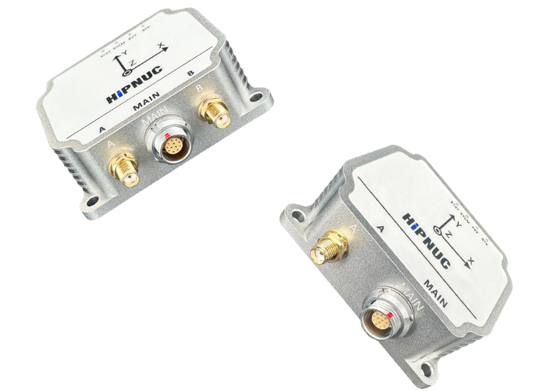
3.1 Product Appearance
3.2 System Block Diagram
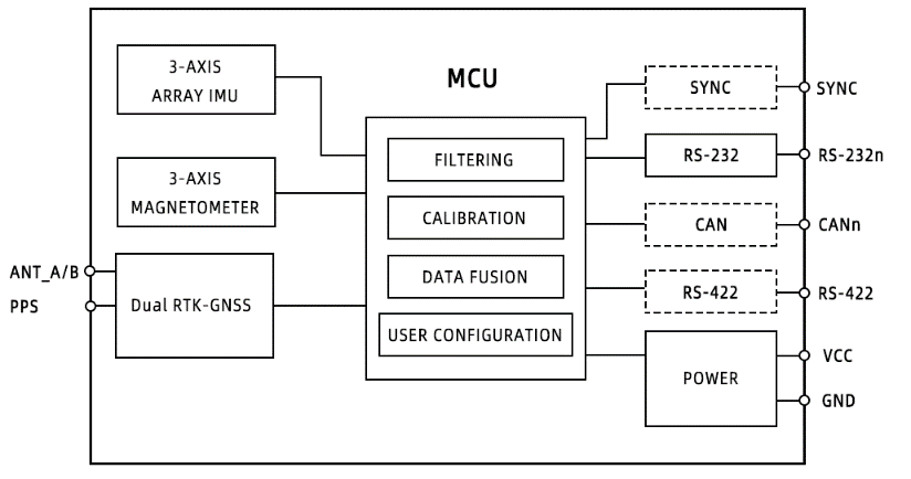
Note: Dashed lines indicate functions that are not supported by all models. See Model Selection for details.
3.3 General Description
The HI32 integrated navigation system combines a high-performance inertial measurement unit (IMU) with an RTK-GNSS receiver and is available in single-antenna and dual-antenna models. Fusion of IMU and GNSS data provides position, velocity, attitude and timing information. See the fusion accuracy table for performance and aiding conditions during GNSS outages.
Each sensor undergoes temperature, bias, scale factor and cross-axis compensation before shipment. The GUI host software supports module configuration, data display, firmware upgrades and data logging.
See Sections 4 and 5 for model selection and ordering information.
4 Model Selection
HI32a-b-cde
Table 1: Model Selection
| Field | Value | Description |
|---|---|---|
| Company Identifier | HI | HiPNUC |
| Product Series | 32 | HI32 Series |
| a: Sensor | R6 | Single-antenna RTK-GNSS/INS |
| a: Sensor | R7 | Dual-antenna RTK-GNSS/INS |
| b: Data Interface | MI0 / MI1 / MI2 | Different interface combinations |
| c: Reserved | 0 | Default |
| d: Connector | 0 | 1T12 circular connector |
| d: Connector | 1 | J30, customization required |
| e: Customization | 0 / Other | Default / OEM |
- Model example:
HI32R7-MI0-000. See Dimensions and Pin Assignments for MI0 and MI1 pin assignments. - The J30 interface requires customization.
- MI2 includes data synchronization pins and requires customization. Confirm the pin assignments and delivered configuration when ordering.
5 Ordering
5.1 Ordering Information
Table 2: Ordering Information
| Model | Product Name | Description |
|---|---|---|
| HI32R6-MI0-000 | Single RTK-GNSS/INS Module | Single-antenna RTK integrated navigation module, 1T12 circular connector, MI0 |
| HI32R7-MI0-000 | Dual RTK-GNSS/INS Module | Dual-antenna RTK integrated navigation module, 1T12 circular connector, MI0 |
| HI32R7-MI1-000 | Dual RTK-GNSS/INS Module | Dual-antenna RTK integrated navigation module, 1T12 circular connector, MI1 |
| HI32R7-MI2-000 | Dual RTK-GNSS/INS Module | Dual-antenna RTK integrated navigation module, 1T12 circular connector, MI2, customization required |
5.2 Contact Us
- Sales Email: sales@hipnuc.com
- Company Website: www.hipnuc.com
6 Document Information
6.1 Applicability
6.1.1 Software and Functions
Available functions and configuration procedures are governed by the applicable command and programming manual and the delivered configuration. For applications requiring external aiding or customized interfaces, confirm the supported scope when ordering.
6.1.2 Hardware Revisions
This datasheet applies to hardware revision C5 and later.
Table 3: Hardware Revision History
| Hardware Revision | Changes |
|---|---|
| C5 | Initial revision |
| C6 | Added antenna power supply protection |
6.2 Document Revision History
Table 4: Document Revisions
| Revision | Date | Author | Changes |
|---|---|---|---|
| 1.0 | 2024-09-06 | HiPNUC | Initial revision |
| 1.1 | 2025-11-15 | HiPNUC | Improved integrated navigation fusion performance |
| 1.2 | 2026-09-30 | HiPNUC | Rebuilt a maintainable source document, aligned specification summaries, referred software configuration to the programming manual, and updated delivery information and resource access |
7 Specifications
Unless otherwise noted, test conditions are 25 °C ambient temperature and 24 V supply voltage.
Sensor ranges, sampling and filtering strategies depend on the delivered configuration. The performance specifications below do not imply that all delivered configurations use fixed sensor settings.
7.1 Absolute Maximum Ratings
Table 5: Absolute Maximum Ratings
| Parameter | Limit | Description |
|---|---|---|
| Mechanical Shock | 2000 g | Duration <1 ms |
| Storage Temperature | −40 to 85 °C | |
| ESD HBM | 15 kV | JEDEC/ESDA JS-001 |
| Input Voltage Vs | 40 V | |
| RS-232 TX to GND | ±13.2 V | |
| RS-232 RX to GND | ±24 V | |
| CAN H or CAN L to GND | ±40 V | |
| CAN H to CAN L | ±27 V | |
| RX+ or RX− to GND | −0.3 to 6 V | |
| TX+ or TX− to GND | −12 to 12 V | |
| SYNC/PPS to GND | −0.3 to 3.6 V |
7.2 Normal Operation
Table 6: Normal Operating Specifications
| Parameter | Minimum | Nominal | Maximum | Unit |
|---|---|---|---|---|
| Input Voltage | 9 | 36 | V | |
| Power Consumption | 1.6 | 2 | W | |
| Operating Temperature | −40 | 85 | °C |
Table 7: Communication Interface Functions
| Interface | Function |
|---|---|
| COM1 / RS-422 | Sensor data input, output and configuration |
| COM2 | Differential correction data input from an external DTU; configurable sensor data output |
| CAN | Sensor data communication |
Physical interfaces depend on the model. See the command and programming manual for protocols, serial port settings and output configuration.
7.3 Interface Specifications
Table 8: PPS/SYNC Levels
| Interface | Parameter | Condition | Minimum | Nominal | Maximum | Unit |
|---|---|---|---|---|---|---|
| PPS/SYNC | Logic Voltage | High | 2.0 | 3.3 | 3.6 | V |
| PPS/SYNC | Logic Voltage | Low | 0.6 | V |
The CAN interface has no built-in 120 Ω termination resistor. See Dimensions and Pin Assignments for RS-232, RS-422 and CAN pins. See the applicable command and programming manual for baud rates, serial data formats, output rates and protocol configuration.
7.4 Gyroscope
Table 9: Gyroscope Specifications
| Parameter | Condition | Nominal | Unit |
|---|---|---|---|
| Bias Instability | Allan Variance | 1.6 | °/h |
| Bias Repeatability | 8 | °/h | |
| Angle Random Walk | Allan Variance | 0.25 | °/√h |
7.5 Accelerometer
Table 10: Accelerometer Specifications
| Parameter | Condition | Nominal | Unit |
|---|---|---|---|
| Bias Instability | Allan Variance | 30 | μg |
| Bias Repeatability | 0.15 | mg | |
| Random Walk | Allan Variance | 0.04 | m/s√h |
7.6 Magnetometer
An integrated magnetometer provides magnetic field measurements.
7.7 GNSS Specifications
| Parameter | Specification | Note |
|---|---|---|
| Channels | 1408 channels | |
| Constellations | BDS / GPS / GLONASS / Galileo / QZSS | |
| BDS Frequencies | B1I / B2I / B3I | |
| GPS Frequencies | L1 C/A / L2P(Y) / L2C / L5 | |
| Galileo Frequencies | E1 / E5a / E5b | |
| GLONASS Frequencies | L1 / L2 | |
| QZSS Frequencies | L1 / L2 / L5 | |
| Cold Start | <30 s | |
| Hot Start | <5 s | 1 |
| Standalone Horizontal Positioning Accuracy (RMS) | 1.5 m | 2, 3 |
| Standalone Vertical Positioning Accuracy (RMS) | 2.5 m | 2, 3 |
| DGPS Horizontal Positioning Accuracy (RMS) | 0.4 m + 1 ppm | 2, 3 |
| DGPS Vertical Positioning Accuracy (RMS) | 0.8 m + 1 ppm | 2, 3 |
| RTK Horizontal Positioning Accuracy (RMS) | 0.8 cm + 1 ppm | 2, 3 |
| RTK Vertical Positioning Accuracy (RMS) | 1.5 cm + 1 ppm | 2, 3 |
| Dual-Antenna Heading Accuracy (RMS) | 0.1°, 1 m baseline | |
| Timing Accuracy (RMS) | 20 ns | |
| Velocity Accuracy (RMS) | 0.03 m/s | 4 |
| Data Update Rate | 20 Hz | |
| Maximum Velocity | 500 m/s | |
| Maximum Altitude | 50000 m |
- Hot start requires a power-off interval of no more than 10 min. Start time depends on the power-off interval; a sufficiently long interval results in a cold start.
- Test results may vary with atmospheric conditions, baseline length, GNSS antenna type, multipath, the number of visible satellites and satellite geometry.
- Measurements are made with a 1 km baseline and a receiver with a well-performing antenna; possible antenna phase center offset errors are not taken into account.
- Velocity accuracy is specified under open-sky, unobstructed conditions, 99% @ static.
7.8 Fusion Specifications
7.8.1 Fusion Algorithm and Data Content
Table 11: Fusion Specifications
| Parameter | Description |
|---|---|
| Data Content | Velocity, position, attitude, time and other information |
| Fusion Algorithm | EKF |
| External Aiding | Differential correction data supplied through an external DTU or similar device; support for other aiding configurations must be confirmed before delivery |
See the command and programming manual for data messages, protocols and differential correction input methods. Physical interfaces and external aiding functions depend on the model and delivered configuration.
7.8.2 Fusion Accuracy
The table below reports results from an odometer-aided test configuration. These results do not imply that all delivered configurations include this aiding function. Applications requiring this GNSS outage performance must confirm odometer connectivity, fusion support and applicable test conditions before delivery.
| GNSS Outage Duration | Positioning and Aiding Conditions | Position Accuracy RMS | Velocity Accuracy RMS | Pitch/Roll Accuracy RMS | Heading Accuracy RMS |
|---|---|---|---|---|---|
| 3 s | RTK + Odometer | 3 cm | 0.03 m/s | 0.15° | 0.1° |
| 10 s | RTK + Odometer | 30 cm | 0.1 m/s | 0.2° | 0.15° |
| 60 s | RTK + Odometer | 3 m | 0.15 m/s | 0.2° | 0.25° |
Test conditions: RTK mode before the GNSS outage, with odometer aiding during the outage.
7.9 Mechanical and Environmental Specifications
Table 12: Mechanical and Environmental Specifications
| Parameter | Specification |
|---|---|
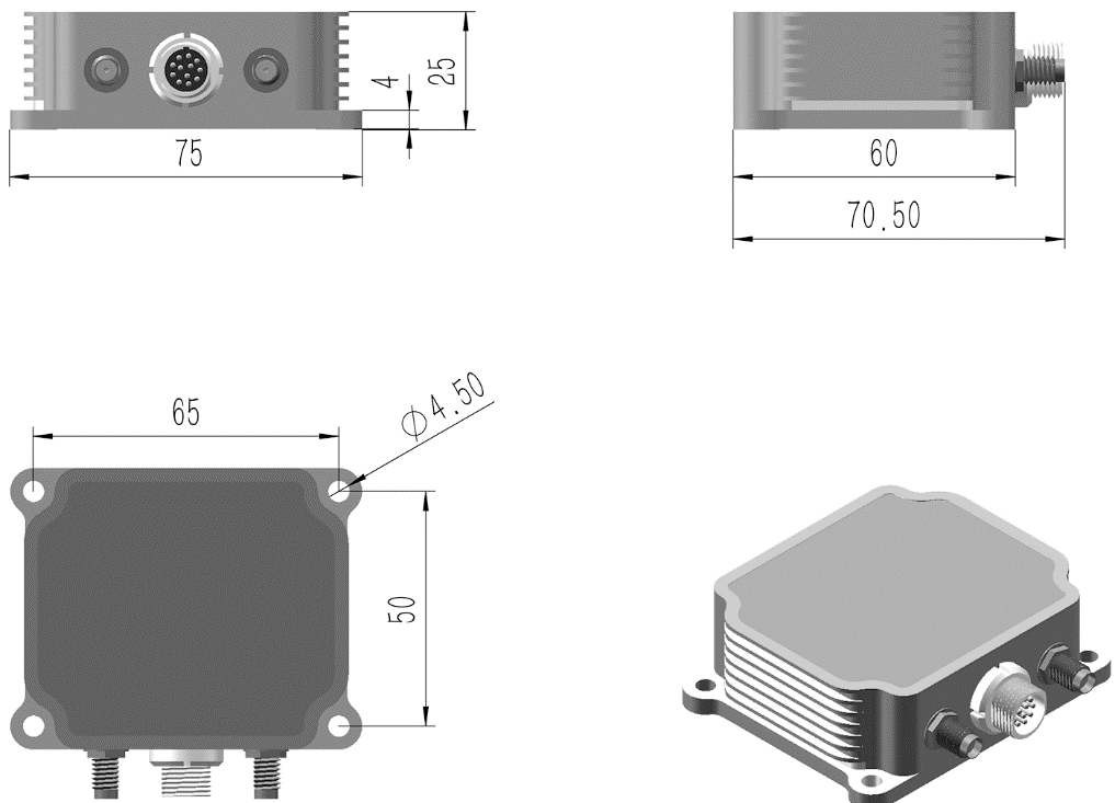
| Dimensions | 75 × 70.5 × 25.2 mm |
| Weight | 180 g |
| Enclosure Material | CNC-machined aluminum alloy |
| Vibration Resistance | 1.0 mm (10 to 58 Hz); ≤20 g (58 to 600 Hz) |
| Environmental Compliance | RoHS Directive 2011/65/EU |
| Drop Test | 3 free falls from a 75 cm-high laboratory bench |
| Temperature Shock | From −40 °C to 85 °C within 1 h, 5 times |
7.10 Dimensions and Pin Assignments
Dimensions in the drawings are in mm.
7.10.1 Product Dimensions
7.10.2 1T12 Circular Connector to DB9 + OPEN (MI0)
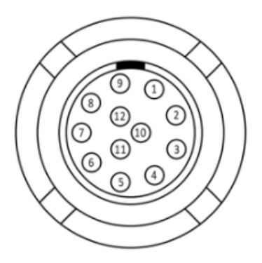
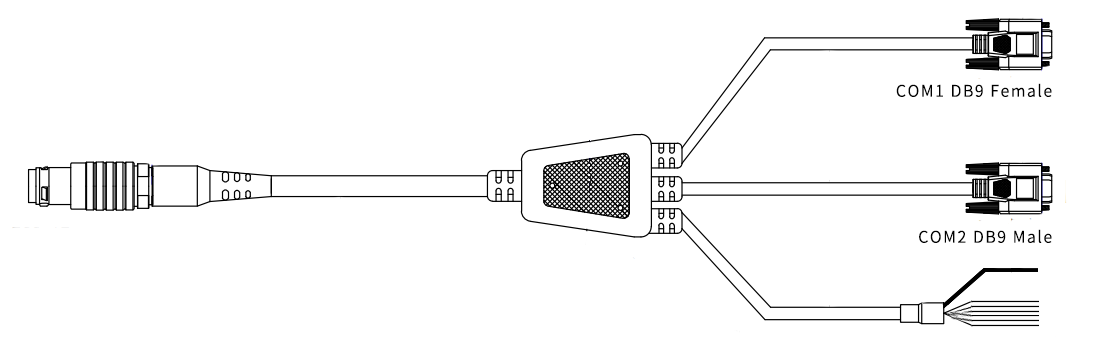
Table 13: MI0 Pin Assignments (DB9 + OPEN)
| Pin | Name | Type | Color | Function | Connection |
|---|---|---|---|---|---|
| 1 | Vs | POWER | Red | Power input 9 to 36 V | OPEN |
| 2 | PGND | POWER | Black | Power ground | OPEN |
| 3 | SGND | POWER | Signal ground | COM1 DB9 female Pin 5 | |
| 4 | RS232-TXD1 | O | COM1 data transmit | COM1 DB9 female Pin 2 | |
| 5 | RS232-RXD1 | I | COM1 data receive | COM1 DB9 female Pin 3 | |
| 6 | CAN1-H | AIO | Brown | CAN1 High | OPEN |
| 7 | CAN1-L | AIO | Purple | CAN1 Low | OPEN |
| 8 | SGND | POWER | Yellow | Signal ground | OPEN |
| 9 | PPS | O | Green | Pulse-per-second signal | OPEN |
| 10 | SGND | POWER | Signal ground | COM2 DB9 male Pin 5 | |
| 11 | RS232-TXD2 | O | COM2 data transmit | COM2 DB9 male Pin 3 | |
| 12 | RS232-RXD2 | I | COM2 data receive | COM2 DB9 male Pin 2 |
- PGND and SGND are internally connected.
- This is the default harness listed in the original datasheet. The delivered harness depends on the order configuration.
7.10.3 1T12 Circular Connector to OPEN (MI0)
Table 14: MI0 Pin Assignments (OPEN)
| Pin | Name | Type | Color | Function |
|---|---|---|---|---|
| 1 | Vs | POWER | Red | Power input 9 to 36 V |
| 2 | PGND | POWER | Black | Power ground |
| 3 | SGND | POWER | Green | Signal ground |
| 4 | RS232-TXD1 | O | Yellow | COM1 data transmit |
| 5 | RS232-RXD1 | I | White | COM1 data receive |
| 6 | CAN1-H | AIO | Brown | CAN1 High |
| 7 | CAN1-L | AIO | Blue | CAN1 Low |
| 8 | SGND | POWER | Gray | Signal ground |
| 9 | PPS | O | Orange | Pulse-per-second signal |
| 10 | SGND | POWER | Purple | Signal ground |
| 11 | RS232-TXD2 | O | Pink | COM2 data transmit |
| 12 | RS232-RXD2 | I | Light Green | COM2 data receive |
PGND and SGND are internally connected.
7.10.4 1T12 Circular Connector to OPEN (MI1)
Table 15: MI1 Pin Assignments (OPEN)
| Pin | Name | Type | Color | Function |
|---|---|---|---|---|
| 1 | Vs | POWER | Red | Power input 9 to 36 V |
| 2 | PGND | POWER | Black | Power ground |
| 3 | SGND | POWER | Green | Signal ground |
| 4 | TX+ | O | Yellow | RS-422 data transmit + |
| 5 | TX- | O | White | RS-422 data transmit − |
| 6 | RX+ | I | Brown | RS-422 data receive + |
| 7 | RX- | I | Blue | RS-422 data receive − |
| 8 | SGND | POWER | Gray | Signal ground |
| 9 | PPS | O | Orange | Pulse-per-second signal |
| 10 | SGND | POWER | Purple | Signal ground |
| 11 | RS232-TXD2 | O | Pink | COM2 data transmit |
| 12 | RS232-RXD2 | I | Light Green | COM2 data receive |
PGND and SGND are internally connected. Verify the pins and wire colors for each interface and harness separately; do not wire one harness using the color assignments of another.
8 Coordinate Systems and Installation
8.1 Coordinate Systems
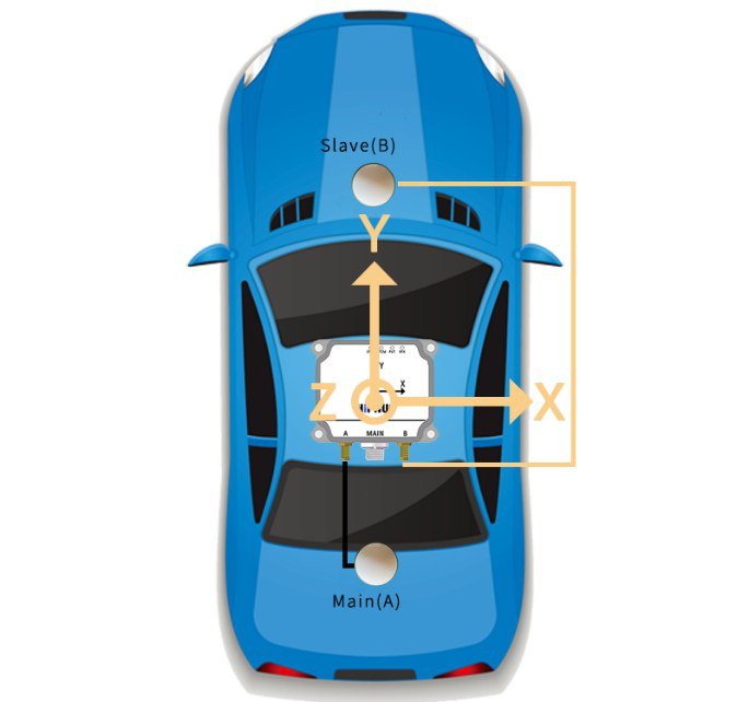
The positive Y-axis points forward along the vehicle, the X-axis points to the right, and the Z-axis points upward. The navigation frame is East-North-Up, and the body frame is Right-Front-Up. The vehicle, GNSS antennas and HI32 must be rigidly connected.
8.2 Sensor and Antenna Installation
For dual-antenna models, A is the primary antenna (positioning antenna), and B is the secondary antenna (heading antenna). Refer to the interface labels on the sensor enclosure. The vector from A to B defines the heading baseline. With the default installation shown, the angle between this baseline and the vehicle's forward direction (positive IMU Y-axis) is 0°, with clockwise rotation defined as positive. The recommended A-to-B antenna spacing is 0.8 to 2 m.
Power-cycle or restart the module after installing the antennas. See the command and programming manual for configuration, saving and verification of antenna lever arms and non-default installations.
8.3 Wiring
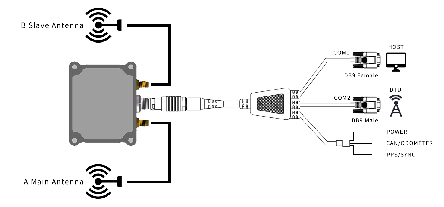
8.3.1 1T12 Circular Connector to DB9 + OPEN
8.3.2 1T12 Circular Connector to OPEN
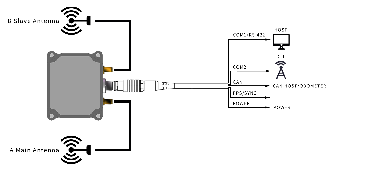
Verify the illustrated interfaces against the model and harness. SYNC requires customization, and odometer aiding support must be confirmed before delivery. The illustrations do not imply that all models provide these functions.
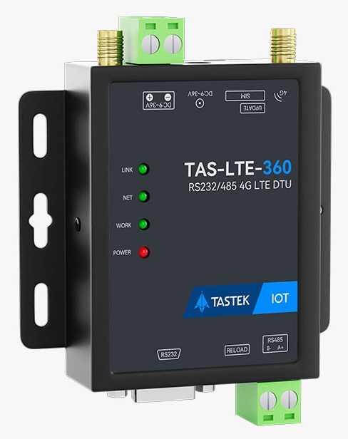
8.3.3 DTU and Differential Correction Data
RTK positioning requires differential correction data. Confirm the DTU model, matching harness and power supply against the order configuration. See the command and programming manual for differential correction input and verification procedures.
9 Initial Configuration
See the applicable INS command and programming manual for serial port parameters, default outputs, operating modes and configuration procedures.
10 Communication Protocols
10.1 Serial Protocols
See the command and programming manual for message types, field definitions and checksum methods. Verify the physical interfaces against the model.
10.2 CAN
See the command and programming manual for CAN protocols, PGNs and configuration procedures.
11 Packaging
The HI32 module is placed in a custom EPE foam insert and then packed in a box. The figure below shows a packing example from the original datasheet.
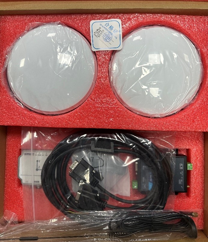
The packing list for the HI32 module, data cables, GNSS antennas, antenna feed cables, magnetic antenna mounts and DTU is governed by the order and delivered configuration.